

Centrifugal separation apparatus and method of using the same
a centrifugal separation and centrifugal technology, applied in centrifuges, gravity filters, loose filtering material filters, etc., can solve the problems of reducing the effective capacity of centrifuges, imposing a considerable down time in operation, and requiring significant maintenan
- Summary
- Abstract
- Description
- Claims
- Application Information
AI Technical Summary
Benefits of technology
Problems solved by technology
Method used
Image

Examples
Embodiment Construction
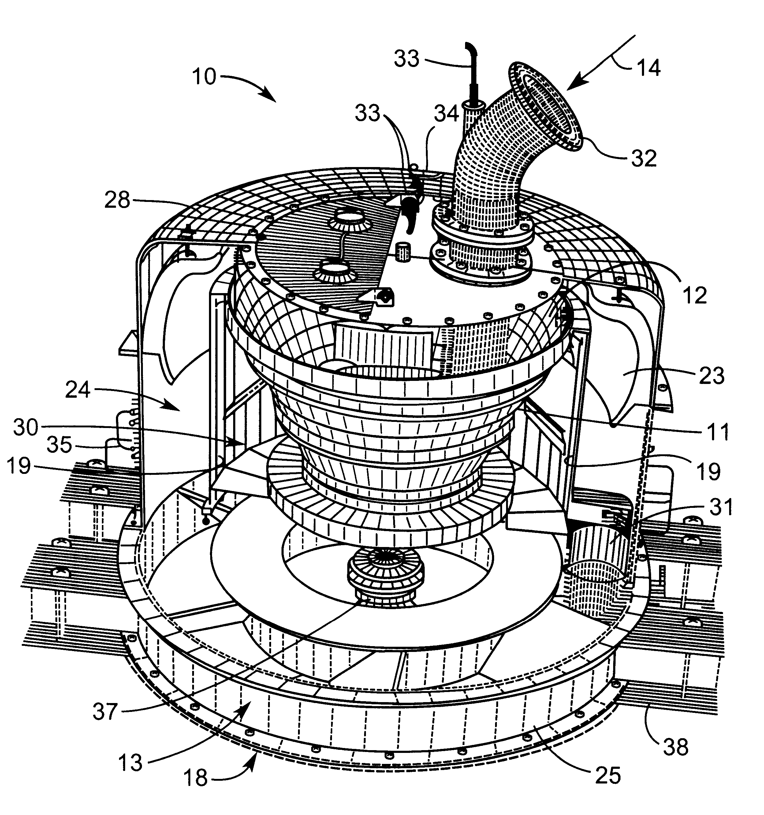
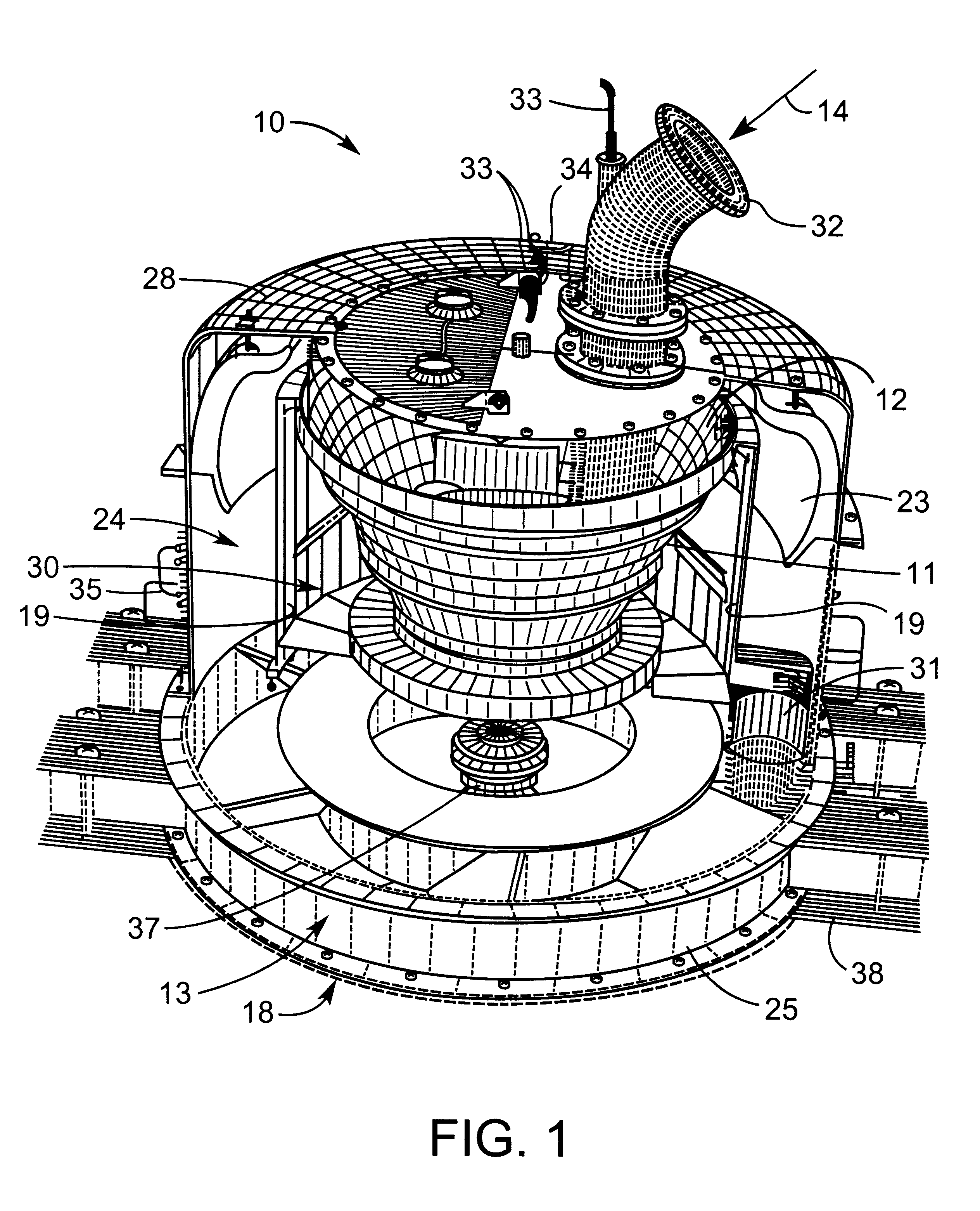
In use the massecuites forms a thin layer which flows progressively up the conical wall of the basket as it is spun at high speed. As a consequence of the centrifugal force applied to the mixture, a thin layer of the mixture is formed which flows up the conical screen with continuous progressive removal of syrup from the mixture through the screen. The filtering and motion of the layer on the screen leads to the classification of crystals with the finer crystals moving towards the screen. The sugar solution passes through the wall of the basket where it is collected in a liquid collection chamber, eg a syrup chamber. A layer of sugar crystals, flows up the conical wall towards the discharge lip. Sugar syrup or water and / or steam may be poured onto the sugar crystals flowing upwardly along the wall of the basket to remove residual syrup from the crystals. This was washing may be accomplished by an arrangement of sprays and a control system which varies the rate of application of spra...
PUM
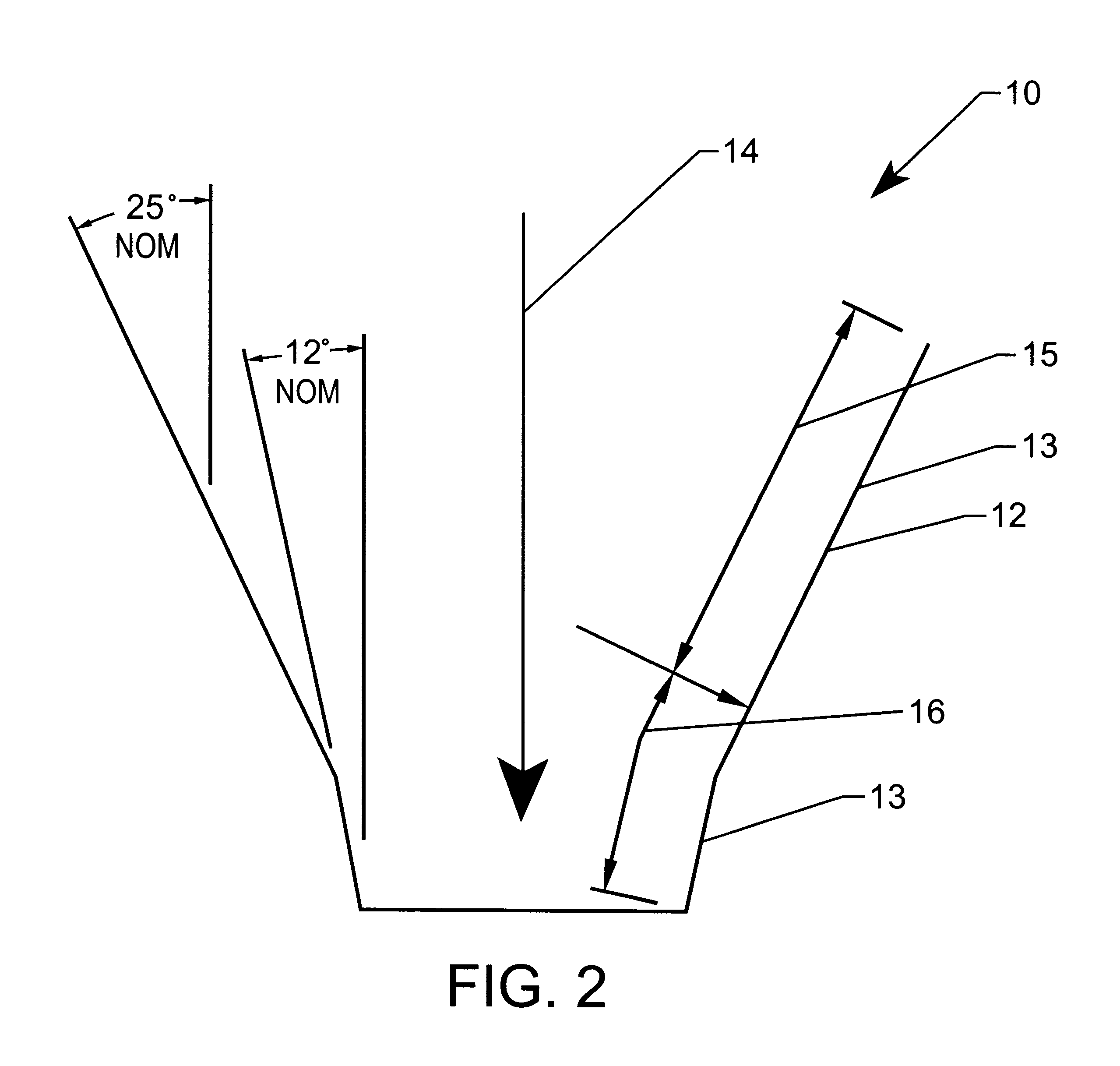
| Property | Measurement | Unit |
|---|---|---|
| angle | aaaaa | aaaaa |
| angle | aaaaa | aaaaa |
| particle size distribution | aaaaa | aaaaa |
Abstract
Description
Claims
Application Information