
Power supply system having semiconductor active fuse

a power supply system and active fuse technology, applied in the direction of dc conversion, transportation and packaging, emergency protective arrangements for limiting excess voltage/current, etc., can solve the problems of large conduction loss of power supply cables, large structure problems, and inability to work

Inactive Publication Date: 2001-07-31
YAZAKI CORP
View PDF15 Cites 63 Cited by
  • Summary
  • Abstract
  • Description
  • Claims
  • Application Information

AI Technical Summary

Problems solved by technology

Thus structure, however, has a problem as follows.
Since larger and larger current flows in the load in recent years, it becomes impossible to ignore the heat dissipation of the shunt resistor, and the conduction loss of the power supply cable becomes large.
This problem is especially serious when larger current is passed through the power supply cable, and in such a case, it is required to install a cooler to the overcurrent controller.
In addition, there is another problem.
However, such functions do not work when a layer short-circuit, or an imperfect short-circuit having some degree of short-circuit resistance occurs so that a low short-circuit current flows through the power supply cable.
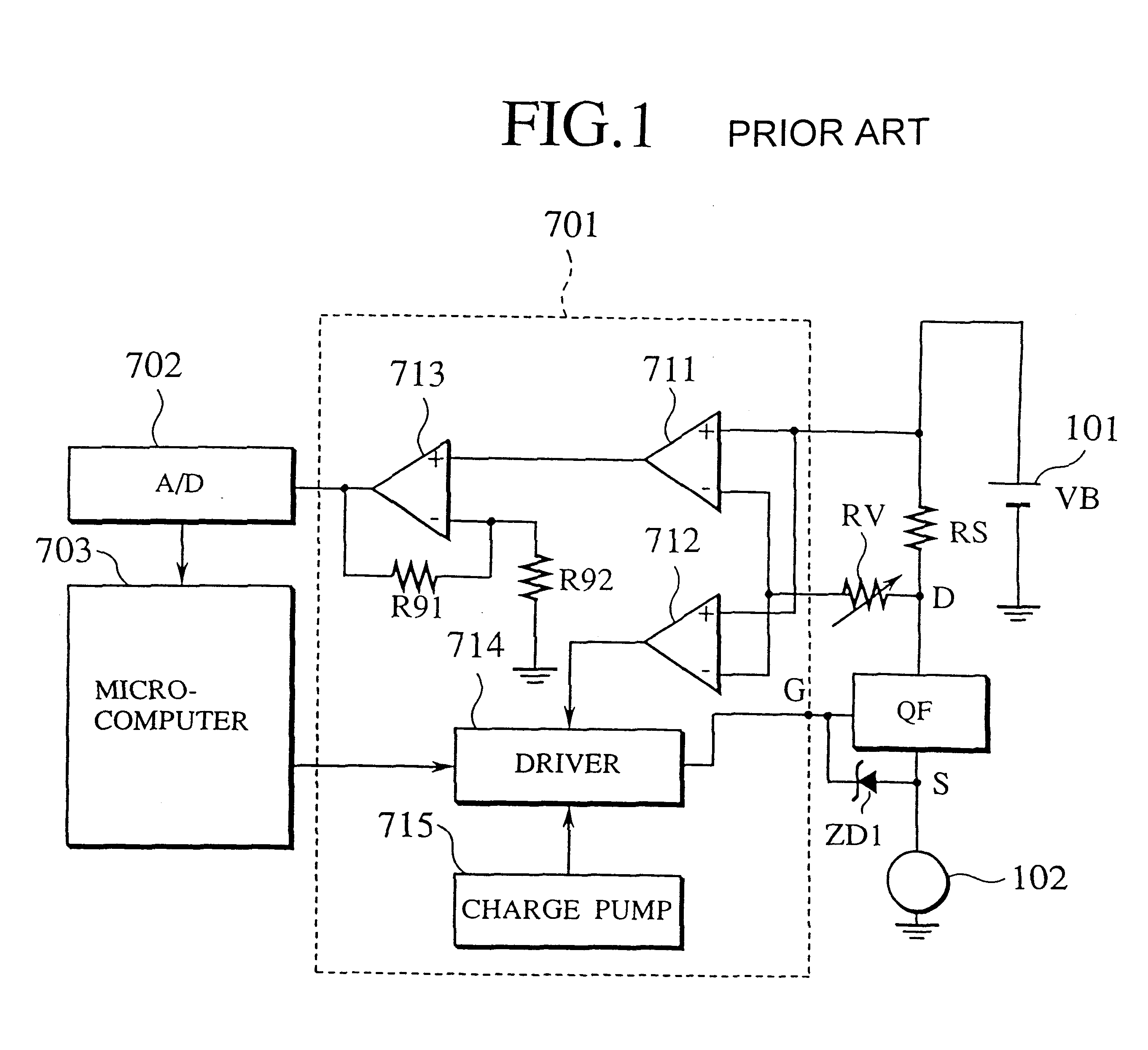
However, this method has a problem that, the current detection of the microcomputer 703 is not so fast that shutting down of the transistor QF may be delayed.
There is also a problem that, in accordance with the necessity to mount the shunt resistor RS, the A / D converter 702, and the microcomputer 703 or the like, a large space is required for the power supply device.
In addition, since these elements are relatively expensive, the cost of the apparatus provided with them becomes high.
Furthermore, there is no reason to exclude another insulated gate power devices such as insulated-gate-bipolar-transistors (JGBTs).
This will bring multiplicity (redundancy) to the power supply system.
Therefore, it has a low on-state resistance, and the total conduction loss is small.

Method used


Image

  • Power supply system having semiconductor active fuse
  • Power supply system having semiconductor active fuse
  • Power supply system having semiconductor active fuse

Examples


second embodiment

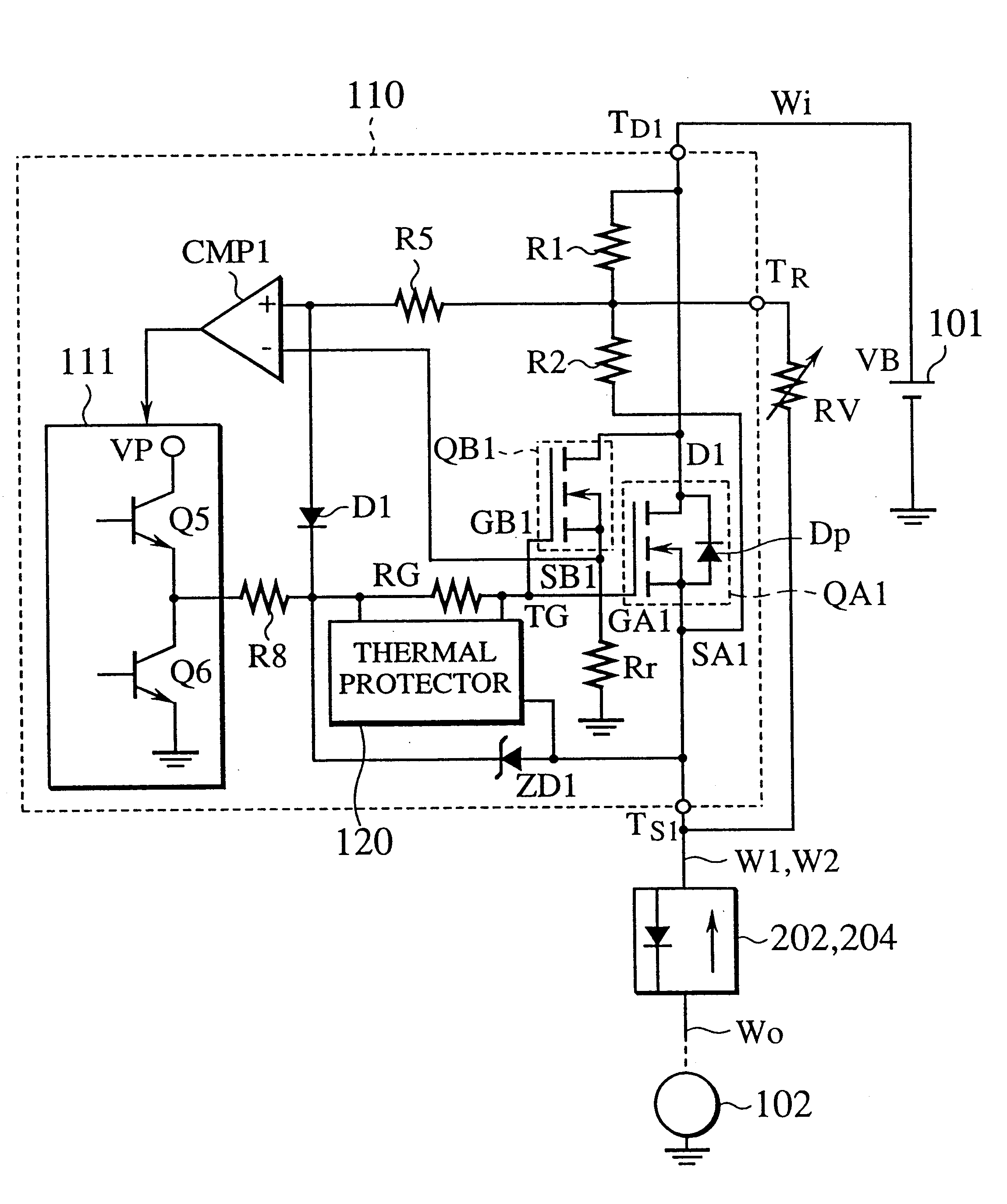
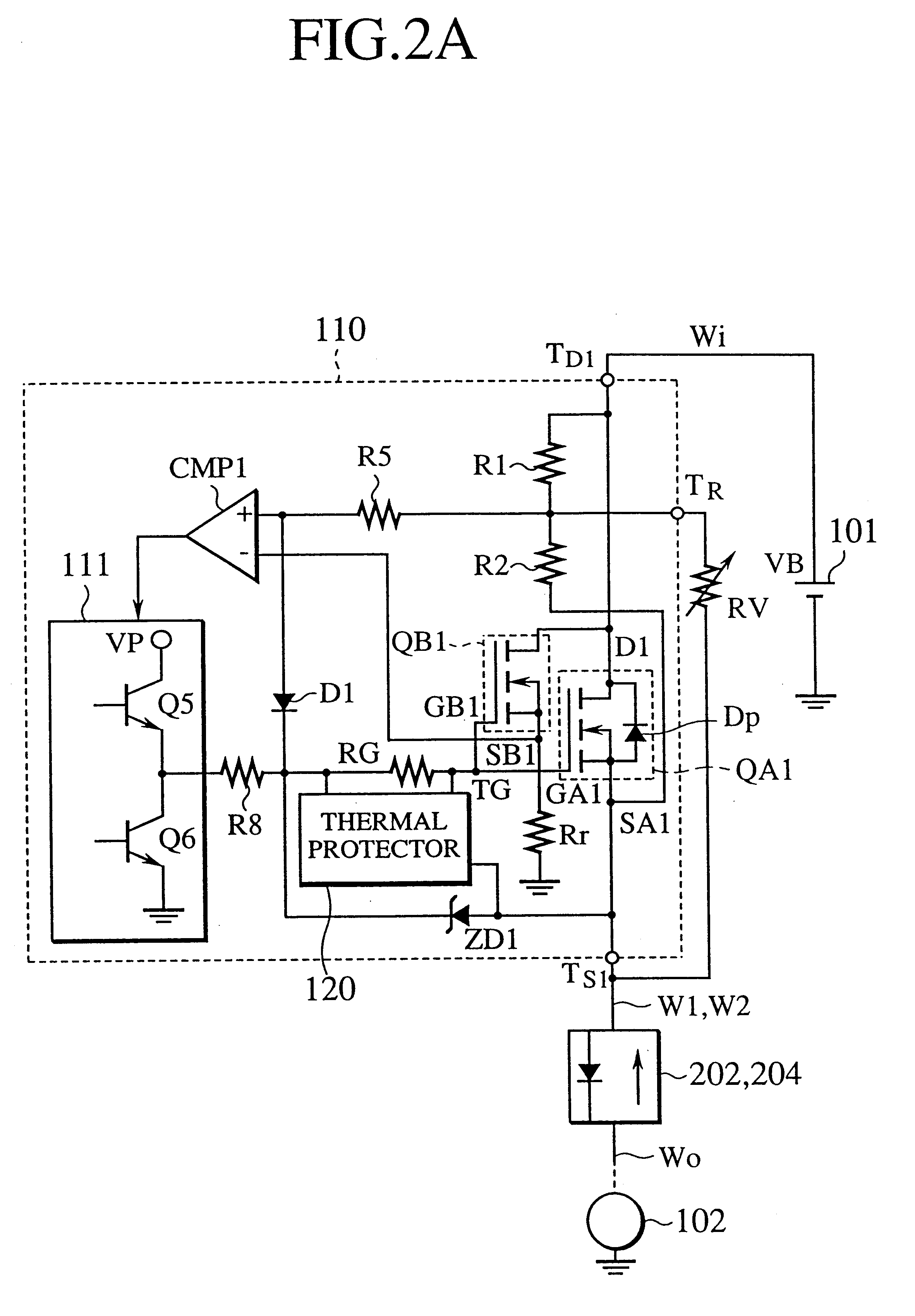
FIG. 9A is a flow diagram schematically showing a power supply system according to a second embodiment of the present invention. As shown in FIG. 9A, the power supply system according to the second embodiment includes two first semiconductor active fuses 201, 203 connected in parallel with each other in a forward direction, a first wire W.sub.1 connected to the respective input terminals T.sub.D of the first semiconductor active fuses 201, 203, two intermediate wires W.sub.1, W.sub.2 respectively connected to output terminals T.sub.s of the first semiconductor active fuses 201, 203, two second semiconductor active fuses 202, 204 arranged in parallel with each other in a reverse direction and having an output terminal T.sub.s connected to the second end of the respective intermediate wires W.sub.1, W.sub.2, a second wire W.sub.0 connected to input terminals T.sub.D of the second semiconductor active fuses 202, 204, a first auxiliary semiconductor active fuse 205 of which input termin...


PUM


Abstract

The power supply system of the present invention includes m first semiconductor active fuses arranged in parallel with each other in a forward direction, a first wire having m branches, each branch is connected to one of m input terminals of the m first semiconductor active fuses, m intermediate wires, each of intermediate wires is connected to one of the first end of the m input terminals of the m first semiconductor active fuses, m second semiconductor active fuses arranged in parallel with each other in a reverse direction, each of the second embodiment active fuses having an output terminal connected to one of the second end of the m intermediate wires, and a second wire having m branches, each branch is connected to one of m input terminals of the m second semiconductor active fuses. Each of the reverse configured m second semiconductor active fuses can conduct the main current forwardly through parasitic diode inherently embodied in the structure. Employing this structure, the present invention provides a power supply system with high reliability.

Description

1. Field of the InventionThe present invention relates to a power supply cable preferable for use in a vehicle to supply electric power from the battery of the vehicle to each section thereof. More specifically, the present invention relates to a power supply cable having "a semiconductor active fuse" which can detect an abnormal current and / or short-circuit failure and if necessary, can cut off the conduction of the current. The present invention also relates to a power supply system having a plurality of the power supply cables.2. Description of the Related ArtFIG. 1 is a diagram showing a conventional power supply system provided with an overcurrent controller installed in a vehicle, where electric power is selectively supplied from the battery to each load of the vehicle, and a transistor QF, having a temperature sensor, controls the supply of the electric power. In the conventional overcurrent controller shown in FIG. 1, the power supply cable extending from a power source 101 ...

Claims


Application Information

Patent Timeline
Patent Type & Authority Patents(United States)
IPC IPC(8): H02H3/087H02H7/26
CPCH02H3/087Y10S323/908H02H7/268H01L29/7802
Inventor OHSHIMA, SHUNZOU
Owner YAZAKI CORP
Learn More