Arrangements for using detected phase differences for setting laser power levels

Inactive Publication Date: 2001-07-31
HITACHI CONSUMER ELECTRONICS CORP
View PDF12 Cites 51 Cited by
  • Summary
  • Abstract
  • Description
  • Claims
  • Application Information

AI Technical Summary

Benefits of technology

As mentioned above, it was found that a ratio of recording threshold power to center value of power margin is approximately constant on sample optical discs having different layer compositions. Also, it was revealed that the detection sensitivity varies in the vicinity of threshold power level depending on recording patterns and the single-pattern repetitive signals provide higher sensitivity and less variation than the random data signals. Through examination of these characteristics on optical disc apparatus, the phase detection method was devised, in whi

Problems solved by technology

In an actual optical disc apparatus, however, even if an output level of a light source is kept constant, it is difficult to provide a required temperature distribution on the information recording side of the optical disc due to adverse effects, e.g., dynamic variations in ambient temperature, laser wavelength, beam spot distortion, etc.
These characteristics in the lower recording power range resulted from a problem owed to the above mentioned recrystallization in recording.
The amount of asymmetry varies differently on the positive and negative sides and it cannot be determined definitely with respect a certain level of recording power, which means that complex processing procedures are required for determination of an optical power level Po using the "asymmetry detection" trial w

Method used


Image

  • Arrangements for using detected phase differences for setting laser power levels
  • Arrangements for using detected phase differences for setting laser power levels
  • Arrangements for using detected phase differences for setting laser power levels

Examples


example 2

Information Recording-Reproducing Apparatus

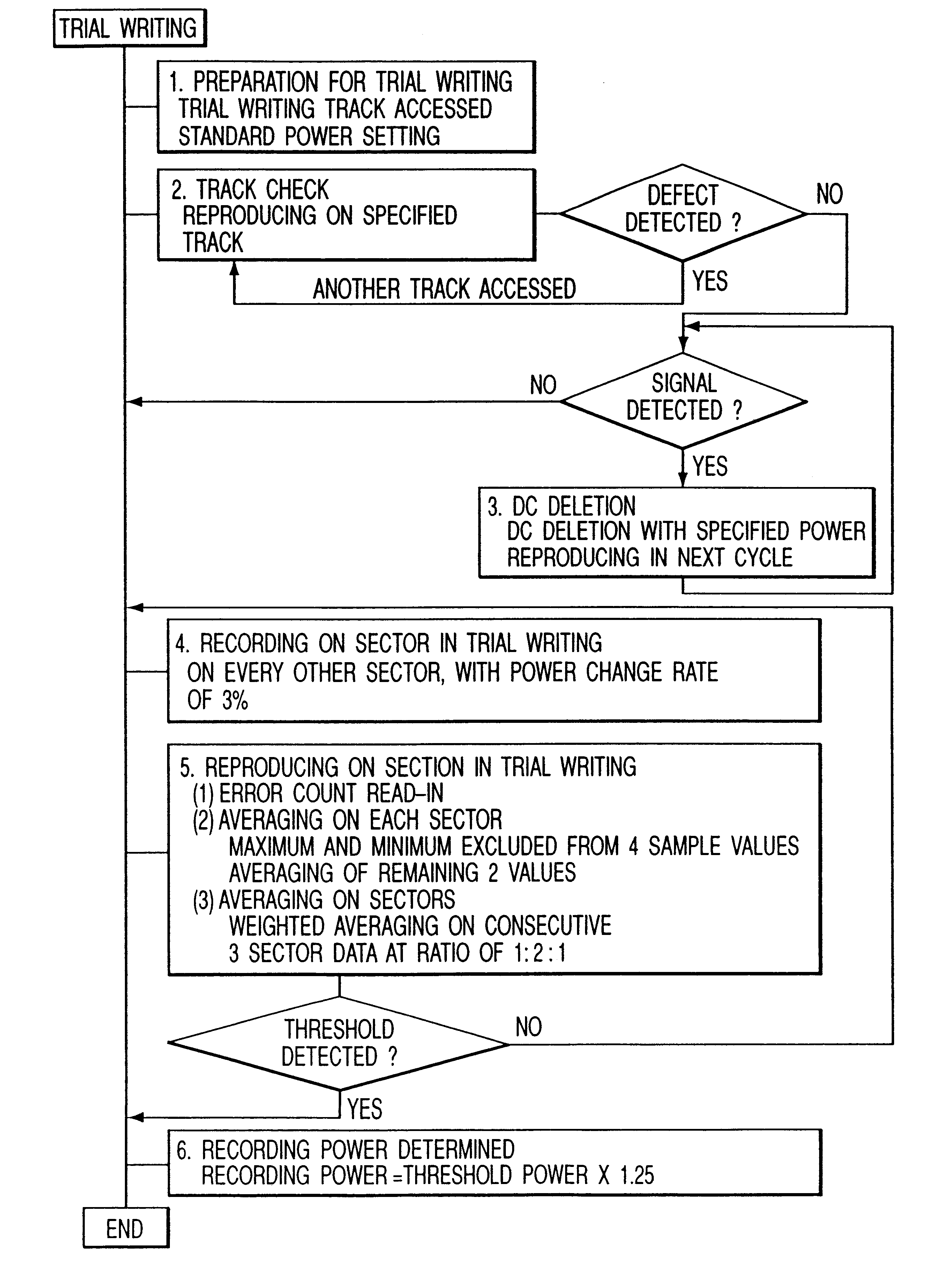
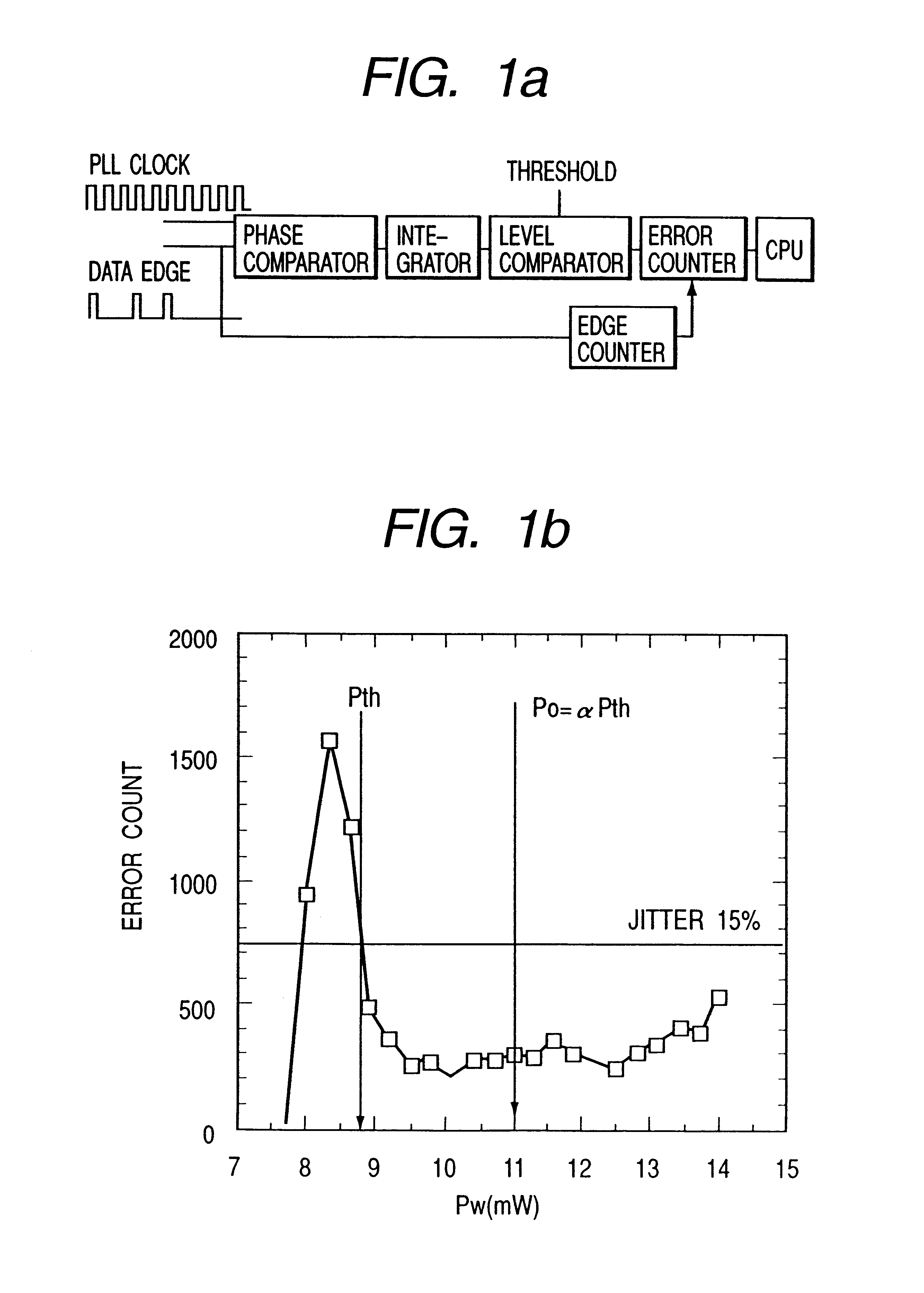
FIG. 14 presents an example of an information recording-reproducing apparatus using the trial writing method and phase difference detection method in the preferred embodiment mentioned in Example 1. Referring to FIG. 14, an optical disc medium 8 is rotated by a motor 162. To provide an intensity level of light instructed by central control means 151, light intensity control means 171 controls light generating means 131 so as to suitably emit a light beam 122. Through focusing means 132, the light beam 122 is focused to form a light spot 7 on the optical disc medium 8. A light beam 123 reflected from the light spot 7 is detected by light detecting means 133. The light detecting means comprises a plurality of divided photodetector elements. Using a reproduced signal 130 from the light detecting means, reproducing means 191 reproduces information recorded on the optical disc medium. The reproducing means 191 contains detecting means for trial ...


PUM


Abstract

For application of asymmetry trial writing onto phase-change recording discs, this invention is intended to determine an optimum level of recording power accurately. Single pattern or random pattern signals are recorded, and phase differences between PLL clock edges and data edges are detected using reproduced signals to determine a threshold value of recording power where a predetermined percentage of phase differences occurs. The threshold power is then multiplied by a constant to provide a optimum level of recording power. Further, there are disclosed arrangements for determining an optimum power condition at a point where an error count (jitter) is minimized, and determining an optimum power condition as an averaged power level existing between low and high power conditions.

Description

The present invention relates to a signal recording method applied to information recording media, a detector circuit for detecting phase differences between recorded / reproduced signals and a reference signal, and an information apparatus using the phase differences to determine a condition for subsequent recording of data on the media, and more particularly to a phase difference technique for determining a laser power level allowing high-density information recording.DISCUSSION OF BACKGROUND ARTA recording-type optical disc is capable of holding a large amount of information and has a feature that it is a replaceable (i.e., swapable) medium. In reproduction of information recorded on the optical disc, a beam of laser light is focused onto an information recording side thereof, and light modulated by a record mark is reflected for detection. In recording of information on the optical disc, a laser beam having a power which is larger than a laser beam power used in reproduction is ap...

Claims


Application Information

Patent Timeline
IPC IPC(8): G11B11/00G11B7/0045G11B11/105G11B7/00G11B7/125
CPCG11B7/0045G11B11/10595G11B7/1267G11B7/00454G11B7/00781G11B20/10407G11B27/24G11B2220/2537
Inventor MINEMURA, HIROYUKITODA, TSUYOSHI
Owner HITACHI CONSUMER ELECTRONICS CORP
Why Eureka
Try Eureka