Three-dimensional acoustic processor which uses linear predictive coefficients

a three-dimensional acoustic processor and predictive coefficient technology, applied in the field of three-dimensional acoustic processors, can solve the problems of insufficient processing capacity, difficult to solve the above-mentioned problems, and impede the reduction of cost and the achievement of a physically compact circui

Inactive Publication Date: 2001-07-31
FUJITSU LTD
View PDF1 Cites 24 Cited by
  • Summary
  • Abstract
  • Description
  • Claims
  • Application Information

AI Technical Summary

Benefits of technology

Another object of the present invention is to provide a three-dimensional acoustic processor in which the acoustic characteristics from a plurality of positions from which a sound image is to be localized are divided into characteristics common to each position and individual characteristics for each position, the filters which add these being disposed in series to control the position of the sound image, thereby reducing the amount of processing performed. In the case in which the sound image is caused to move, by localizing a single sound image at a plurality of locations and controlling the difference in acoustic output level between the different locations, the sound image is smoothed therebetween, interpolation being performed between the positions of the visual image which moves discontinuously, thereby achieving moving of the sound image which matches the thus interpolated positions. In addition, a three-dimensional acoustic processor is provided wherein, in the case in which a reproducing sound image is reproduced using a DSP (digital signal processor) or like, to avoid complexity of registers and like, and to perform the desired sound image localization, localization processing is performed for only the required virtual sound source.
According to the present invention, by compensating for the waveform of the synthesis filter impulse response in the time domain, it is easy to control the difference in level between the two ears. By doing this, it is possible to reduce the number of filters without changing the overall acoustic characteristics, making a DSP implementation easier, and further it is possible to reduce the amount of required memory capacity by only performing localization processing for the required virtual sound sources for the purpose of localizing the desired sound image.

Problems solved by technology

Therefore, when using FIR filters, there is a huge number of taps and computation required, causing the problems that in an actual circuit implementation it is necessary to have a plurality of parallel DSPs or convolution processors, this hindering a reduction in cost and the achievement of a physically compact circuit.
In addition, in the case of localizing the sound image, it is necessary to perform parallel processing of a plurality of channel filters for each of the sound image positions, making it even more difficult to solve the above-noted problems.
Additionally, in an image-processing apparatus which processes images which have accompanying sound images, such as in real-time computer graphics, the amount of image processing is extremely great, so that if the capacity of the image-processing apparatus is small or many images must be processed simultaneously, the insufficient processing capacity produces cases in which it is not possible to display a continuous image, and the image appears as a jump-frame image.
In such cases, there is the problem that the movement of the sound image, which is synchronized to the movement of the visual image, becomes discontinuous.
In addition, in cases in which the environment is different from the expected visual / auditory environment of, for example, the user's position, there is the problem of the apparent movement of the visual image being different from the movement of the sound image.

Method used


Image

  • Three-dimensional acoustic processor which uses linear predictive coefficients
  • Three-dimensional acoustic processor which uses linear predictive coefficients
  • Three-dimensional acoustic processor which uses linear predictive coefficients

Examples


Embodiment Construction

Before describing the present invention, the technology related to the present invention will be described, with reference made to the accompanying drawings FIG. 1 through FIG. 10B.

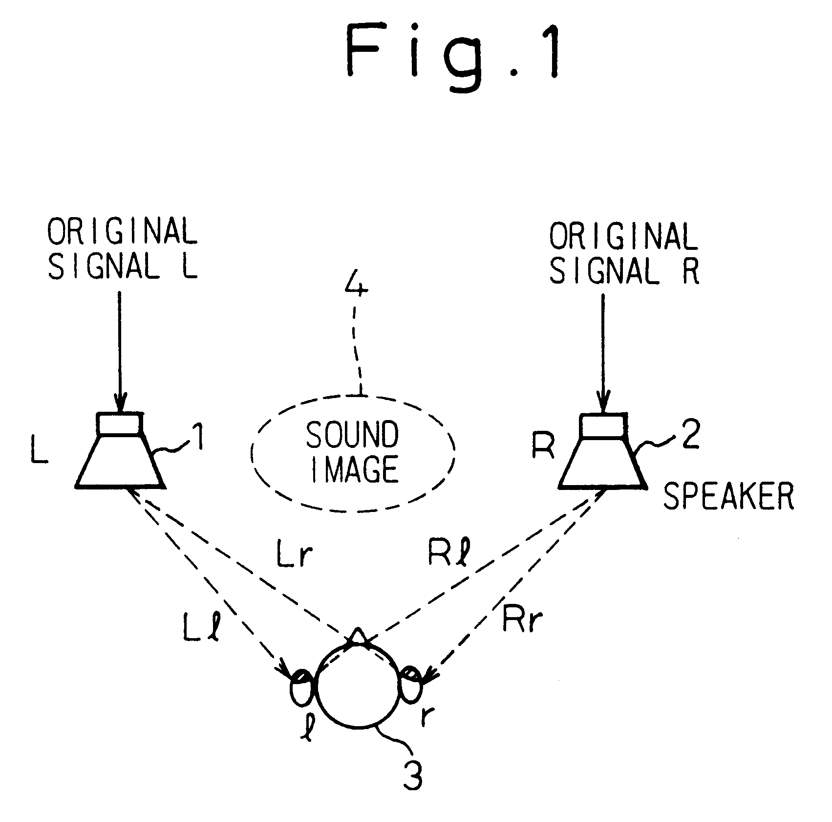
FIG. 1 shows the case of listening to a sound image from a two-channel stereo apparatus in the past.

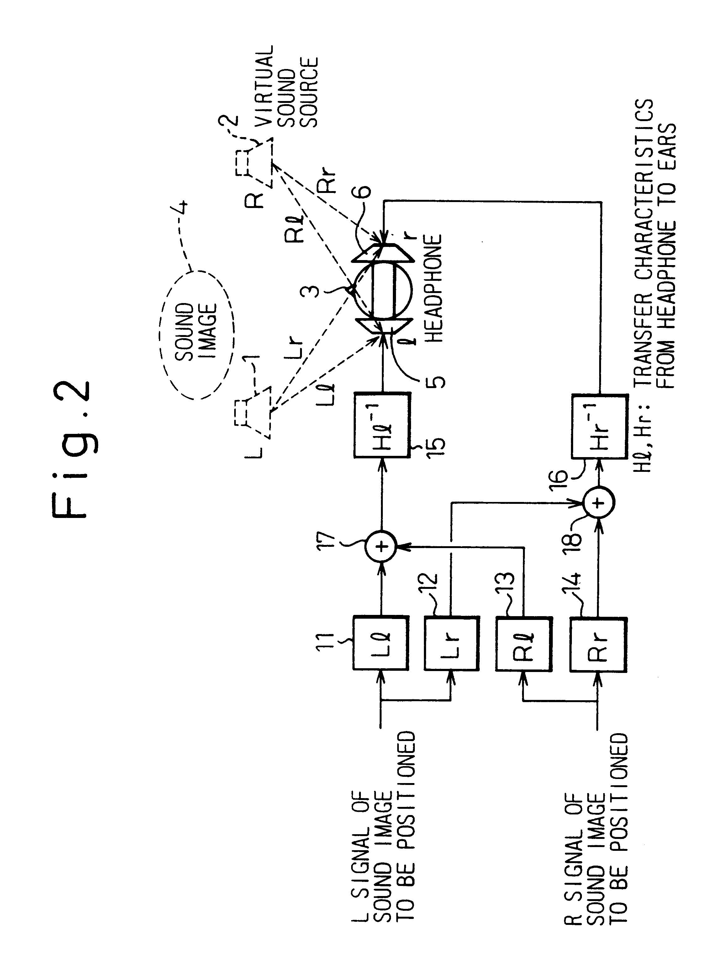
FIG. 2 shows the basic block diagram circuit configuration which achieves an acoustic space that is equivalent to that created by the headphone in FIG. 1.

In FIG. 1, the transfer characteristics for each of the acoustic space paths from the left and right speakers (L, R) 1 and 2 to the left and right ears (l, r) of the listener 3 are expressed as Ll, Lr, Rr, and Rl. In FIG. 2, in addition to the transfer characteristics 11 through 14 of each of the acoustic space paths, the inverse characteristic (Hl.sup.-1 and Hr.sup.-1) 15 and 16 of each of the characteristics from the left and right earphones of headphone (HL and HR) 5 and 6 to the left and right ears are added.

As shown in FIG. 2, by adding the above-note...


PUM


Abstract

To provide a three-dimensional acoustic effect to a listener in a reproduction field, via a headphone in particular, a three-dimensional acoustic apparatus is formed by a linear synthesis filter having filter coefficients that are the linear predictive coefficients obtained by performing a linear predictive analysis on an impulse response which represents the acoustic characteristics to be added to the original signal to achieve this effect. By passing the signal through this acoustic characteristics adding filter, the desired acoustic characteristics are added to the original signal, and by dividing the power spectrum of the impulse response of these acoustic characteristics into critical bandwidths and performing this linear predictive analysis based on impulse signal determined based from power spectrum signals representing the signal sound of each of these critical bandwidths, the filter coefficients of the linear synthesis filter are determined.

Description

1. Field of the InventionThe present invention relates to acoustic processing technology, and more particularly to a three-dimensional acoustic processor which provides a three-dimensional acoustic effect to a listener in a reproducing sound field via a headphone or the like.2. Description of Related ArtIn general, to achieve accurate reproduction or location of a sound image, it is necessary to obtain the acoustic characteristics of the original sound field up to the listener and the acoustic characteristics of the reproducing sound field from the acoustic output device, such as a speaker or a headphone, to the listener. In an actual reproducing sound field, the former acoustic characteristics are added to the sound source and the latter characteristics are removed from the sound source, so that even using a speaker or a headphone it is possible to reproduce to the listener the sound image of the original sound image of the original sound field, or so that it is possible to accurat...

Claims


Application Information

Patent Timeline
Patent Type & Authority Patents(United States)
IPC IPC(8): H04S1/00H04S7/00
CPCH04S1/002H04S1/005H04S1/007H04S2420/01H04S7/302
Inventor MATSUO, NAOSHISUZUKI, KAORI
Owner FUJITSU LTD
Why Eureka
Try Eureka