Gas detecting sensor and device for controlling ventilation systems

a technology of gas detection sensor and ventilation system, which is applied in the direction of instruments, vessel parts, vessel construction, etc., can solve the problems of increasing the size and cost of the gas detection device, the inability to sense two kinds of exhaust gases, and the difficulty of separating the sensor signal generated due to gasoline exhaust gas from the sensor signal generated

Inactive Publication Date: 2001-08-21
SENSIRION AUTOMOTIVE SOLUTIONS KOREA CO LTD
View PDF4 Cites 30 Cited by
  • Summary
  • Abstract
  • Description
  • Claims
  • Application Information

AI Technical Summary

Problems solved by technology

This typical gas detecting sensor has a defect that it cannot sense two kinds of exhaust gases generated by a gasoline vehicle and a diesel vehicle all together.
However, if two sensors are used, a sensor installation structure and a sensing circuit should be constituted in dual, thereby increasing the size and cost of the gas detecting device.
However, when only one sensor is used, it is difficult to separate a sensor signal generated due to gasoline exhaust gas from a sensor signal generated due to diesel gas exhaust gas.
Besides, complicated sensor signal conversion and signal processing is required.
Moreover, when using the sensor having a metallic oxide compound, it may happen that the sensor wrongly senses polluted air and performs a wrong operation with respect to the ventilation system if very harmful material has influenced the sensor device at constant concentration for a long time, for example, if the vehicle has been parked in a very polluted underground parking lot for a long time.

Method used


Image

  • Gas detecting sensor and device for controlling ventilation systems
  • Gas detecting sensor and device for controlling ventilation systems
  • Gas detecting sensor and device for controlling ventilation systems

Examples


Embodiment Construction

Reference will now be made in detail to the preferred embodiments of the present invention, examples of which are illustrated in the accompanying drawings.

With reference to the accompanying drawings, the embodiments of the present invention will now be described in detail.

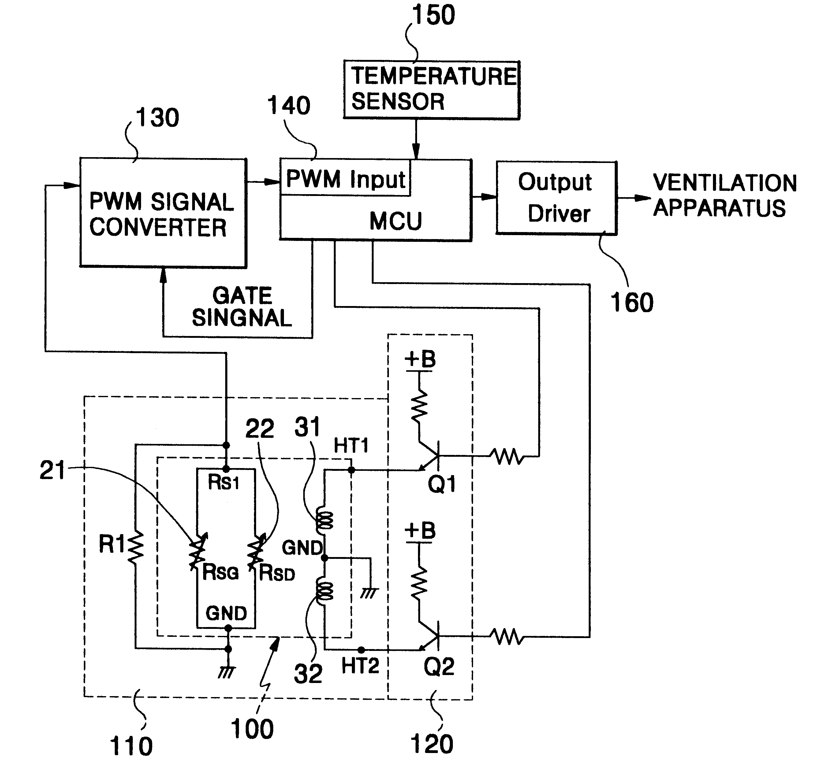
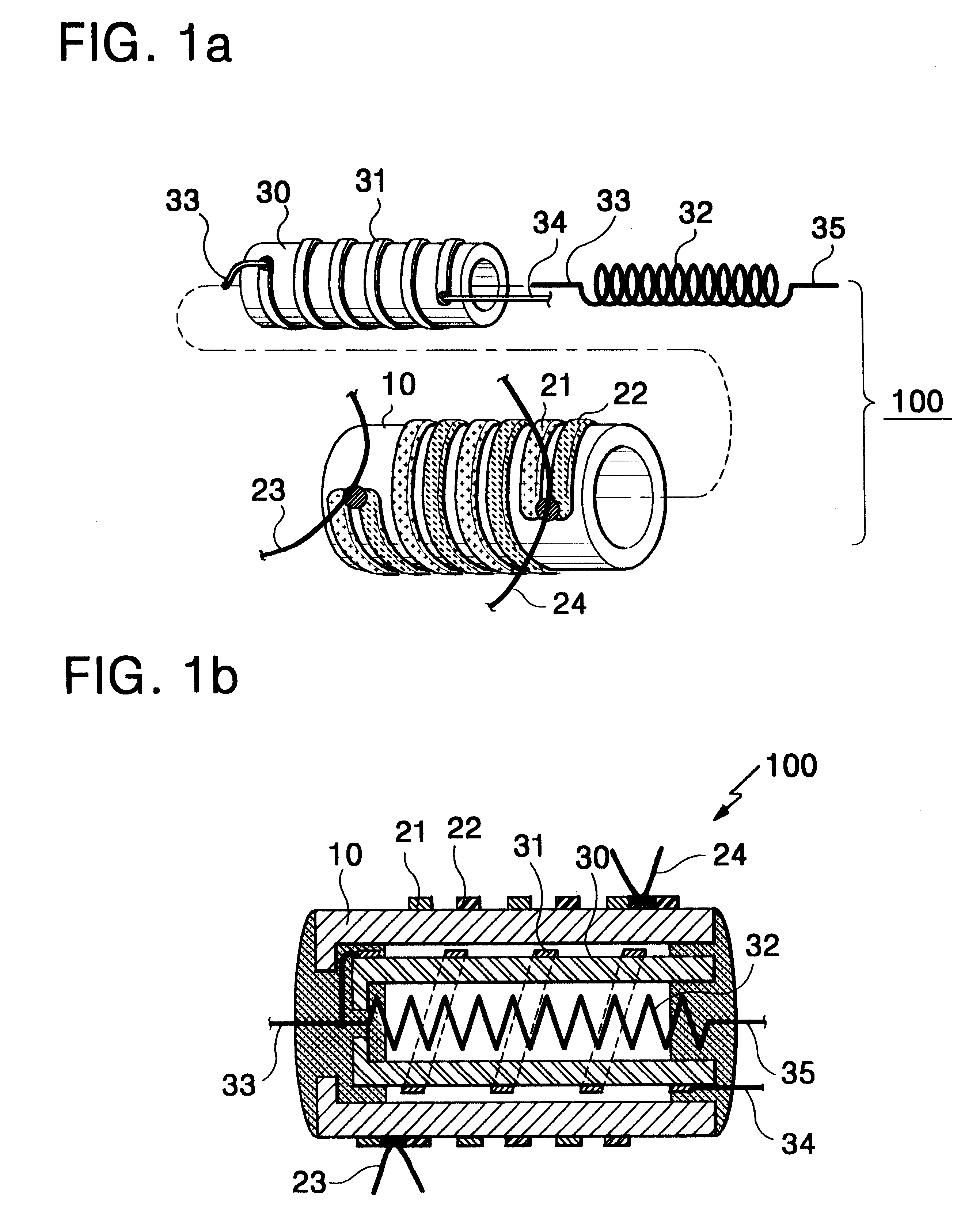
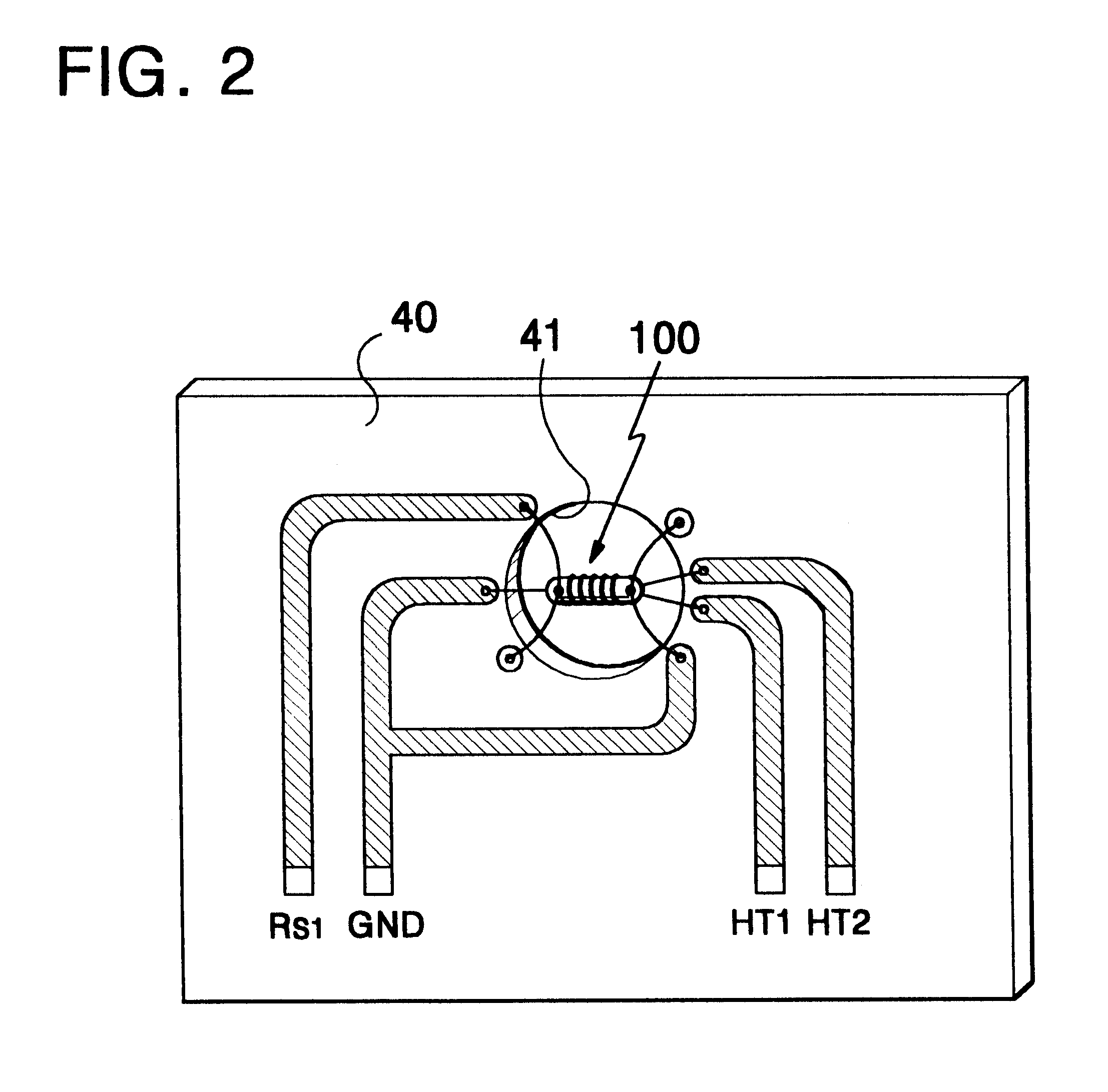
FIG. 1 shows a structure of a gas detecting sensor according to the present invention. As shown in FIG. 1, the gas detecting sensor comprises: a sensor body 10 which is formed of a ceramic cylinder and constitutes a trunk of the sensor; first and second sensing layers 21 and 22 that are separately doped around the outer circumference of the sensor body 10, have variable internal resistance values by respectively reacting to a gasoline exhaust gas and a diesel exhaust gas, and have both ends respectively connected to sensor wires 23 and 24 in common; and first and second heaters 31 and 32 that are inserted into the sensor body 10 and heat the first and second sensing layers 21 and 22 respectively reacting to the gas...


PUM

PropertyMeasurementUnit
temperaturesaaaaaaaaaa
resistanceaaaaaaaaaa
conductiveaaaaaaaaaa

Abstract

There are provided with a gas detecting sensor and a gas detecting device for controlling a ventilation system of a vehicle using the gas detecting sensor. The gas detecting sensor of the present invention includes two kinds of gas sensing layers separately formed and a heater assembly for heating the two sensing layers to different temperatures. The gas detecting device includes: a sensor signal detecting unit for detecting a gas based upon a parallel resistance value obtained by connecting the two kinds of sensing layers of the gas detecting sensor to each other in parallel; a heater drive unit for periodically adjusting the heater to a gasoline exhaust gas sensing temperature and to a diesel exhaust gas sensing temperature; a pulse width modulation (PWM) signal converting unit for generating a differential waveform signal corresponding to the variation of a parallel resistance from the sensor signal detecting unit and converting the differential waveform signal into a PWM signal; and a control unit for controlling the heater drive unit and the PWM signal converting unit, receiving and estimating a sensor signal in the form of a digital signal of the PWM signal, determining a pollution level based upon the estimation, and controlling a ventilation system.

Description

1. Field of the InventionThe present invention relates to an improved digital gas detecting device for detecting a pollution level of the air in the vicinity of a vehicle and controlling a ventilation system of the vehicle, and more particularly, to a gas detecting sensor having a novel structure for detecting concentrations of a gasoline gas and a diesel gas and a gas detecting device for estimating a pollution level of the air around a vehicle using the gas detecting sensor and controlling a ventilation system.2. Description of Related ArtA typical gas detecting sensor is a semiconductor sensor using tin dioxide as an active layer. This typical gas detecting sensor has a defect that it cannot sense two kinds of exhaust gases generated by a gasoline vehicle and a diesel vehicle all together. To sense both exhaust gases together, two sensors should be used. A tin dioxide (SnO.sub.2) sensor is used to detect the gasoline exhaust gas and a tungsten trioxide (WO.sub.3) sensor is used t...

Claims


Application Information

Patent Timeline
Patent Type & Authority Patents(United States)
IPC IPC(8): B60H3/00G01N27/12G01N33/00G01N27/18
CPCB60H1/008G01N27/123B60H3/0085G01N27/18
Inventor SIM, HAE KYUNGLIM, CHEOL
Owner SENSIRION AUTOMOTIVE SOLUTIONS KOREA CO LTD
Why Eureka
Try Eureka