
Air manager apparatus and method for exhausted equipment and systems, and exhaust and airflow management in a semiconductor manufacturing facility

a semiconductor manufacturing facility and equipment technology, applied in ventilation systems, heating types, separation processes, etc., can solve the problems of insufficient "pull" of exhaust equipment and system exhaust, insufficient airflow velocity to significantly increase airflow velocity over a chemical, and occasional fume spillage into the process and operator environment, etc., to achieve sufficient airflow, reduce energy consumption, and increase efficiency

Inactive Publication Date: 2001-08-28
ADVANCED TECH MATERIALS INC
View PDF13 Cites 25 Cited by
  • Summary
  • Abstract
  • Description
  • Claims
  • Application Information

AI Technical Summary

Benefits of technology

to provide such exhausted equipment and systems exhaust system, having increased efficiency, generating sufficient airflow for hazardous fume containment while consuming less energy.
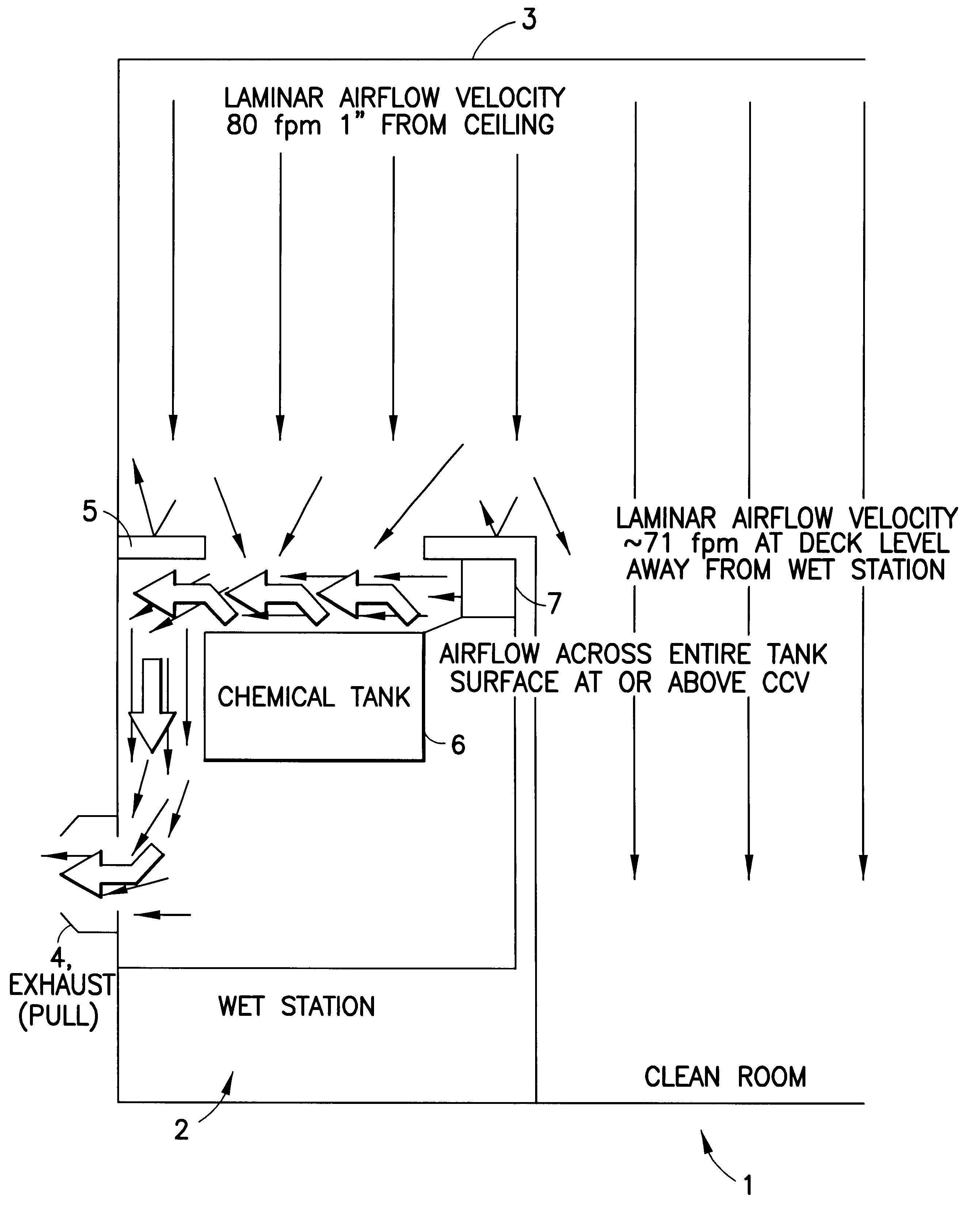
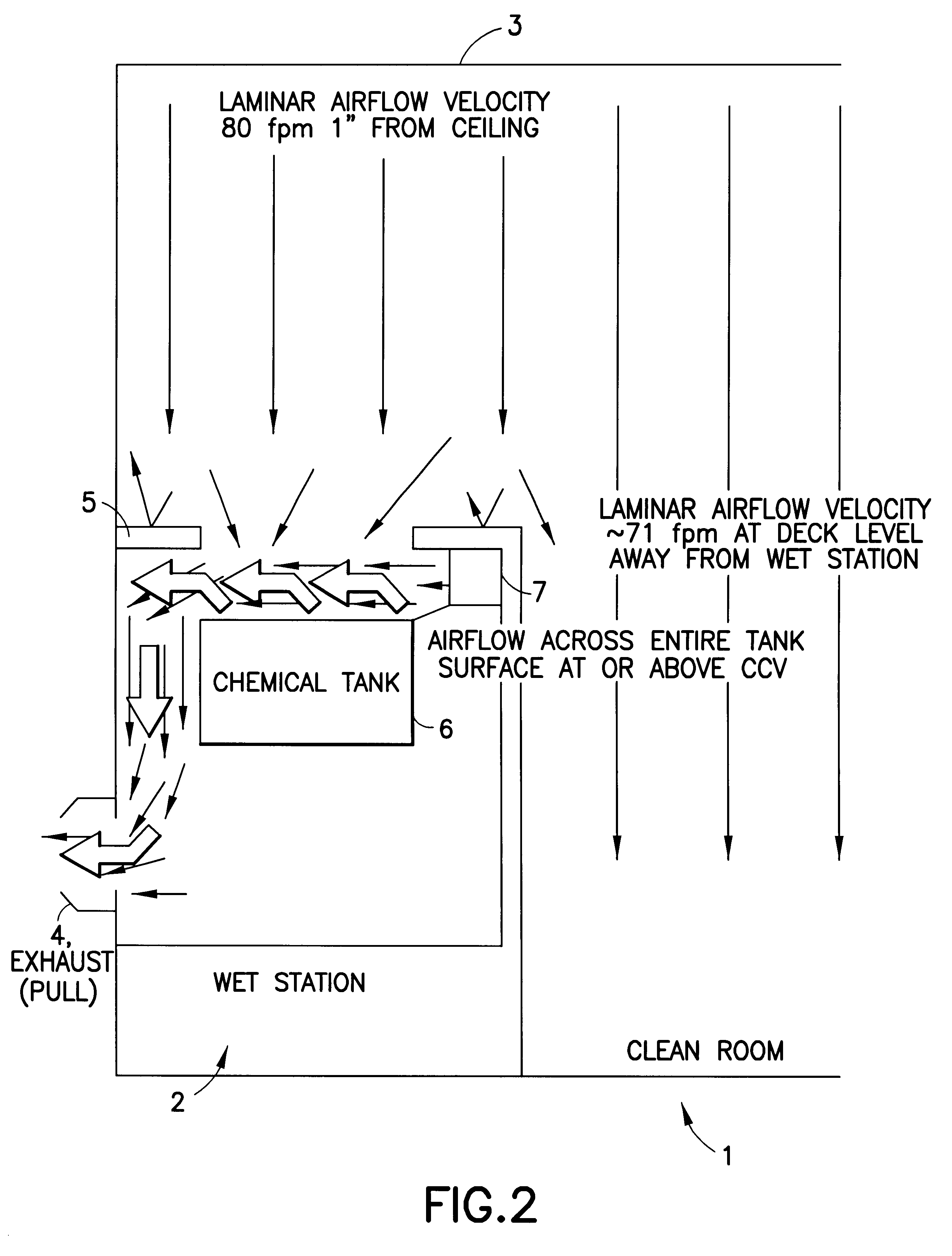
It is a further object of the present invention to provide an exhausted equipment and systems exhaust system that assures maintenance of CCV at values of 70 fpm or greater.
It is still a further object of the present invention to provide an exhausted equipment and systems exhaust system that provides control of hazardous fumes outside the process envelope region of the facility and outside of the operator's breathing zone.

Problems solved by technology

Many semiconductor manufacturing process steps involve the use of chemicals that are toxic or otherwise hazardous to humans, necessitating localized exhaust equipment to remove, contain, or otherwise abate fumes from such chemicals.
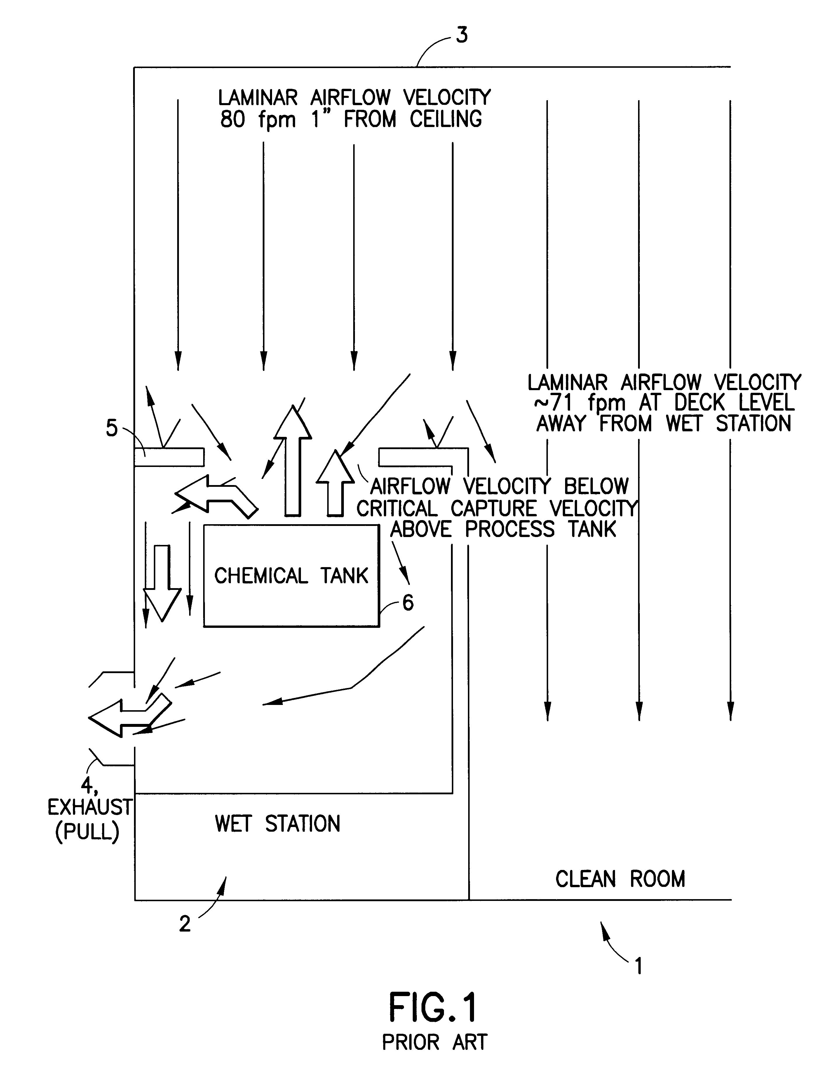
At the same time, the exhausted equipment and system exhaust "pull" is insufficient to significantly increase airflow velocity over a chemical tank.
Because of these factors, most exhausted equipment and systems exhibit marginal flume capture capability, and many fail to consistently control contamination and hazardous fumes at the deck, resulting in occasional fumes spills into the process and operator environment.
As wafer sizes used in the semiconductor industry grow to 300 mm or more and require larger deck openings, however, CCV becomes more difficult to achieve, and facility exhaust capacity is stretched beyond its limits.
Conventional push-pull systems will not be able to produce enough combined force to achieve capture of hazardous fumes in large size wafer facilities now under design and construction.
Additionally, many 200-millimeter (mm)-exhausted equipment and systems in current use are unable to achieve CCV because of a disparity in the exhaust capacity, deck opening sizes, and laminar push.
Consequently, fume spill incidents occur in many wafer fabs, resulting in yield loss, excessive rework, process disruption, environmental and regulatory noncompliance, injury, and litigation.

Method used


Image

  • Air manager apparatus and method for exhausted equipment and systems, and exhaust and airflow management in a semiconductor manufacturing facility
  • Air manager apparatus and method for exhausted equipment and systems, and exhaust and airflow management in a semiconductor manufacturing facility
  • Air manager apparatus and method for exhausted equipment and systems, and exhaust and airflow management in a semiconductor manufacturing facility

Examples


example

The air management system of the invention was evaluated in a semiconductor manufacturing facility wet system including a deck that was 128.5 inches in length, overlying a series of process tanks, comprising in sequence a chuck wash tank, a NH.sub.4 OH tank, two rinse tanks, two HF tanks, and two rinse tanks.

The NH.sub.4 OH tank and one of the HF tanks were studied by velocity profile and fog visualization tests. The deck openings for these tanks were each 11 inches by 15.5 inches. The NH.sub.4 OH tank was 16.5 inches wide by 26 inches long, and the HF tank had the same dimensions. Each tank was 11.75 inches tall, and the spacing distance between the upper end of the tank walls and the deck was 6.5 inches. The exhaust box for each tank had an exhaust duct opening 8 inches in diameter.

Measurements were taken at the deck opening above the process tank in each case. The deck opening above each process tank was divided into an imaginary 4.times.3 grid, and measurements were taken in the...


PUM

PropertyMeasurementUnit
velocityaaaaaaaaaa
sizesaaaaaaaaaa
velocityaaaaaaaaaa

Abstract

An air manager for the containment of hazardous fumes over a liquid chemical tank in exhausted equipment and systems in a clean room. A powered, filtered airflow source forces filtered air through a plenum coextensive with a transverse dimension of the chemical tank, in a sheet-like airflow stream over the liquid surface. The airflow is captured at the opposite side of the liquid chemical tank and directed to a powered exhaust. The air manager works cooperatively with the clean room laminar airflow, dramatically increasing the efficiency of the local exhaust. Critical Capture Velocity over the entire surface of the tank is maintained, assuring complete containment of chemical fumes. Optional airflow guides positioned along the sides of the chemical tank may be employed to confine the air stream to the area over the liquid surface.

Description

1. Field of the InventionThe present invention generally relates to airflow in controlled environments. More particularly, the present invention relates to improved process equipment exhaust and airflow management in clean room and mini-environment enclosures.2. Description of the Related ArtSemiconductor manufacturing must be performed in a particle-free environment, due to the fact that submicron size dimensions characterize the structural elements of the electronic circuitry and such circuitry can be rendered inoperative by the presence of even a single particle. Semiconductor manufacturing process steps are therefore carried out within the confines of a clean room, a controlled environment in which the air is continuously filtered to remove dust, lint, and other particulate matter. Processes and apparatuses for managing forced airflow in clean rooms and other environmentally controlled enclosures are well known in the art.U.S. Pat. No. 6,007,595, issued to Baik, et al. on Dec. 2...

Claims


Application Information

Patent Timeline
Patent Type & Authority Patents(United States)
IPC IPC(8): B01D53/74F24F3/16H01L21/00F24F7/00F24F7/06F24F7/003H01L21/306
CPCB01D53/74F24F3/161H01L21/6715H01L21/67017F24F2007/001Y10S55/29Y10S55/18F24F3/167F24F7/003
Inventor WALKER, BRUCE
Owner ADVANCED TECH MATERIALS INC
Learn More