Optical package with alignment means and method of assembling an optical package

a technology of optical package and optical package, which is applied in the field of optical device package, can solve the problems of time-consuming and expensive process, add to the overall cost of led or laser package, and achieve the effect of maximum power transmission

Inactive Publication Date: 2001-09-04
STRATOS INT
View PDF9 Cites 91 Cited by
  • Summary
  • Abstract
  • Description
  • Claims
  • Application Information

AI Technical Summary

Benefits of technology

It is a further object of the present invention to provide an optical device package which may be easily aligned with an optical transceiver housing.
It is another object of the present invention to provide an optical package housing formed using insert molding techniques in order to provide a quickly and inexpensively manufactured precision housing assembly.
It is still yet another object of the invention to provide an optical device package having a sleeve which prevents galling and is inexpensively manufactured.
In a further embodiment, a plastic housing provides an improved mechanism for aligning the mating optical waveguide with the plastic optical package. A split bore feature is incorporated with a first optical waveguide receiving bore. The split bore embodiment contemplates at least one narrow slot formed in the optical waveguide receiving bore, extending from the receiving end of the bore toward the base of the bore near the point where a focusing element is mounted. The slot or slots allow the walls of the housing to flex as the waveguide is inserted into the bore. Precision alignment of the waveguide is only necessary at the base end of the bore adjacent the focusing element. The flexibility of the bore sidewalls diminishes toward the end of the slots. Thus, as an optical waveguide is inserted into the bore, the increasing rigidity of the sidewalls gradually forces the waveguide to the precision alignment position at the base of the bore. This arrangement has the advantages of simplifying the mating procedure of the waveguide to the housing, and reducing the area of precision molding necessary to properly align the waveguide, thereby reducing the cost of molding the plastic housing.

Problems solved by technology

The hermetic sealing of the TO can is a time-consumsing and expensive process which adds to the overall expense of the LED or laser package.
Thus, placement of the TO can in a uniform position does not provide for alignment of the diode to an optical connector and maximum power transmission is not achieved.
Thus, alignment of the TO package becomes a time-consuming and expensive process.
Such an optical transceiver housing is often rendered ineffective in production due to variations in the alignment of the LED or laser relative to the TO can.
The close fit between the metallic housing and the ceramic ferrule has resulted in a failure mode known as galling.
Galling results in large amounts of material transfer between one or both of the contacting surfaces.
At a certain point, the galling phenomenon is so insidious that it prevents the ferrule from being further inserted into the housing or from being removed from the housing of the optics housing.
Machining a ceramic material to exacting dimensional requirements is difficult and hence is expensive.
The scrap rate is high and the time required to process such ceramic sleeves is high.

Method used


Image

  • Optical package with alignment means and method of assembling an optical package
  • Optical package with alignment means and method of assembling an optical package
  • Optical package with alignment means and method of assembling an optical package

Examples


Embodiment Construction

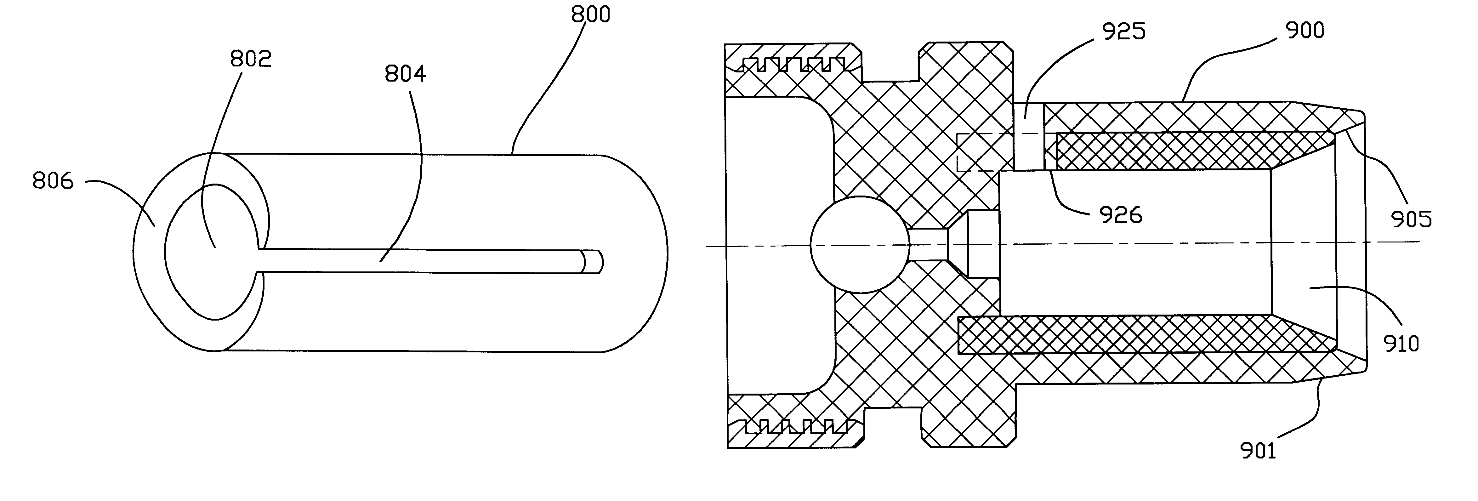
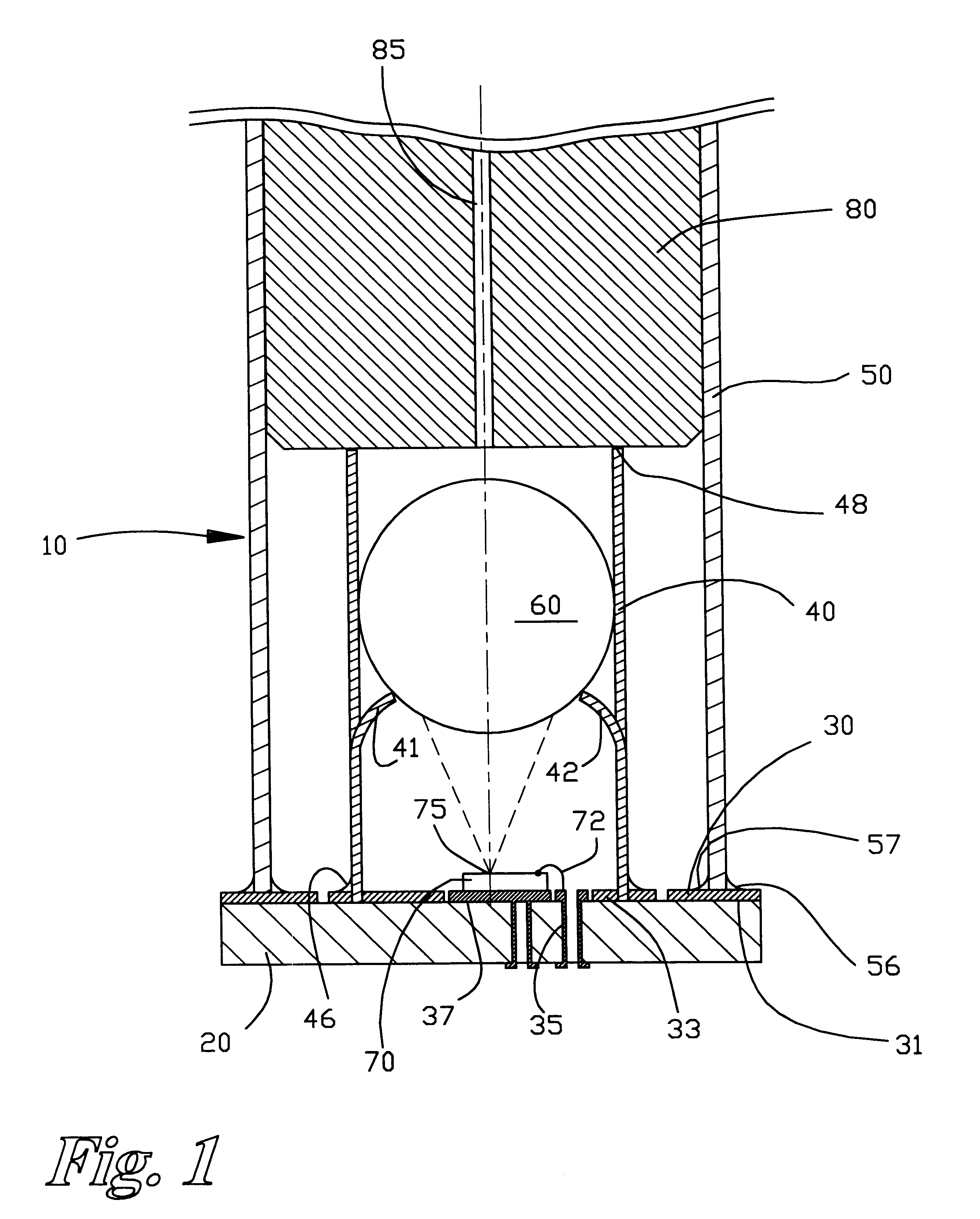
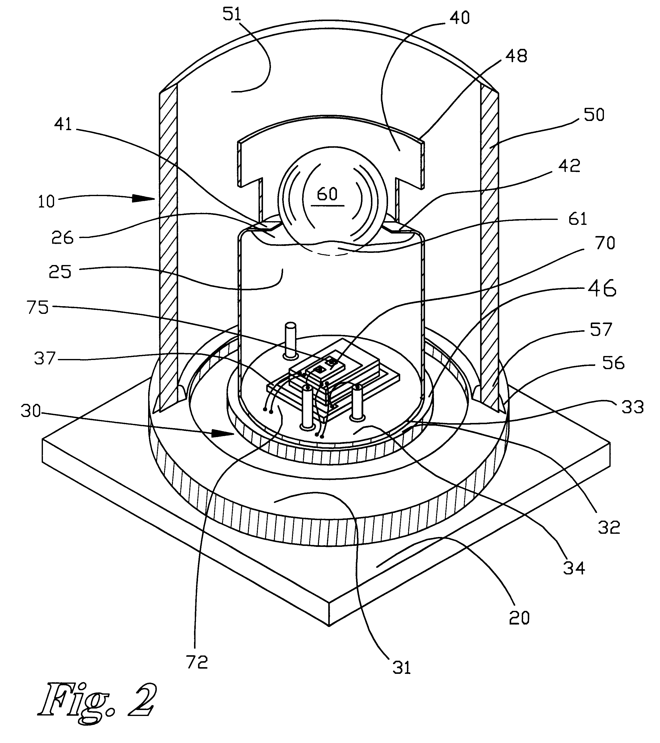
The present invention, as shown in FIG. 1, relates to an optical package housing 10 comprising a substrate 20 having an alignment means such as traces 30 adhered thereto. Mounted to the substrate 20 is inner sleeve 40 and outer sleeve 50. Mounted within the inner sleeve 40 is ball lens 60 and optical device or diode 70. Received within the outer sleeve 50 is optical waveguide ferrule 80 including optical fiber 85. The present invention may be better understood by a description of a preferred embodiment of assembling the optical package housing 10. The substrate 20, for example, FR4, has traces 30, such as conductive four ounce copper traces adhered thereto. For example, a subtractive etching process or an additive process such as vacuum deposition may be used to pattern the substrate 20. The conductive traces 30 are adhered in a predetermined orientation providing for an outer trace 31, a sleeve groove 33 and also forming through-holes 35. The through-holes 35 provide retention poin...


PUM


Abstract

An optical package is provided including a housing having first and second ends. A ferrule receiving bore is formed in the first end, and an optics cavity is formed in the second end. The optics cavity and the ferrule receiving bore are axially aligned with one another along an optical axis defined by the package. A mounting cap is inserted over the optics cavity and frictionally engages an outer surface of the housing. The end cap includes an endplate and a substrate having an optical device mounted thereon. The ferrule receiving bore includes a longitudinal slot extending generally parallel to the axis of the bore providing radial flexibility to the outer wall. Additionally, a split sleeve is provided for accepting a fiber optic connector ferrule. The split sleeve being insertable and expandable in a ferrule receiving bore of an optical package housing. The split sleeve being retained in the ferrule receiving bore with an adhesive.

Description

1. Field of the InventionThis invention pertains generally to optical transceivers and, in particular, to an optical device package for an optical transceiver.2. Discussion of the BackgroundOptical transceivers are known in the art and include active optical devices or diode packages. Common diode packages include LED packages such as a TO-46 package or a 5.6 mm TO style laser diode package such as RLD-85PC diode package by Rohm, Incorporated. These diode packages or TO cans typically include a metallic housing having a laser diode or LED for transmitting data and a photo diode for performing power-monitoring, metal contact leads exiting from the diodes for connection to a power source and a cover glass opposed to the diode, through which the energy is transmitted. The TO can is hermetically sealed. The hermetic sealing of the TO can is a time-consumsing and expensive process which adds to the overall expense of the LED or laser package. As well, the commonly known TO cans do not ha...

Claims


Application Information

Patent Timeline
Patent Type & Authority Patents(United States)
IPC IPC(8): G02B6/36G02B6/42
CPCG02B6/4204G02B6/4225G02B6/4292G02B6/4237G02B6/4238H01L2224/48091H01L2924/3025H01L2924/00014H01L2924/00G02B6/4244G02B6/4245G02B6/4251G02B6/4263
Inventor GILLILAND, PATRICK B.SHATSKIN, LEONIDWEISS, ROGERERICKSON, SCOTTWASHBURN, THEODORE
Owner STRATOS INT
Why Eureka
Try Eureka