Method and device for recording a refractive index pattern in an optical medium
a technology of refractive index and optical medium, which is applied in the field of devices and methods for recording refractive index patterns in optical mediums, can solve the problems of difficult control of methods, limit the length of refractive index gratings that can be formed, and limit the length of fibres that can be exposed in this way
- Summary
- Abstract
- Description
- Claims
- Application Information
AI Technical Summary
Problems solved by technology
Method used
Image
Examples
fourth embodiment
Referring now to FIG. 6, the invention is shown, in which a chirped refractive index grating is recorded in a spiral planar waveguide 22 which is formed in the surface of a silica plate 23, in a manner well known per se. For example, the silica plate 23 may be provided with a photosensitive surface coating by Ge:B co-doping techniques, which is then photo etched to form the spiral pattern. It will be seen that the waveguide 22 is arranged generally concentric with point X.
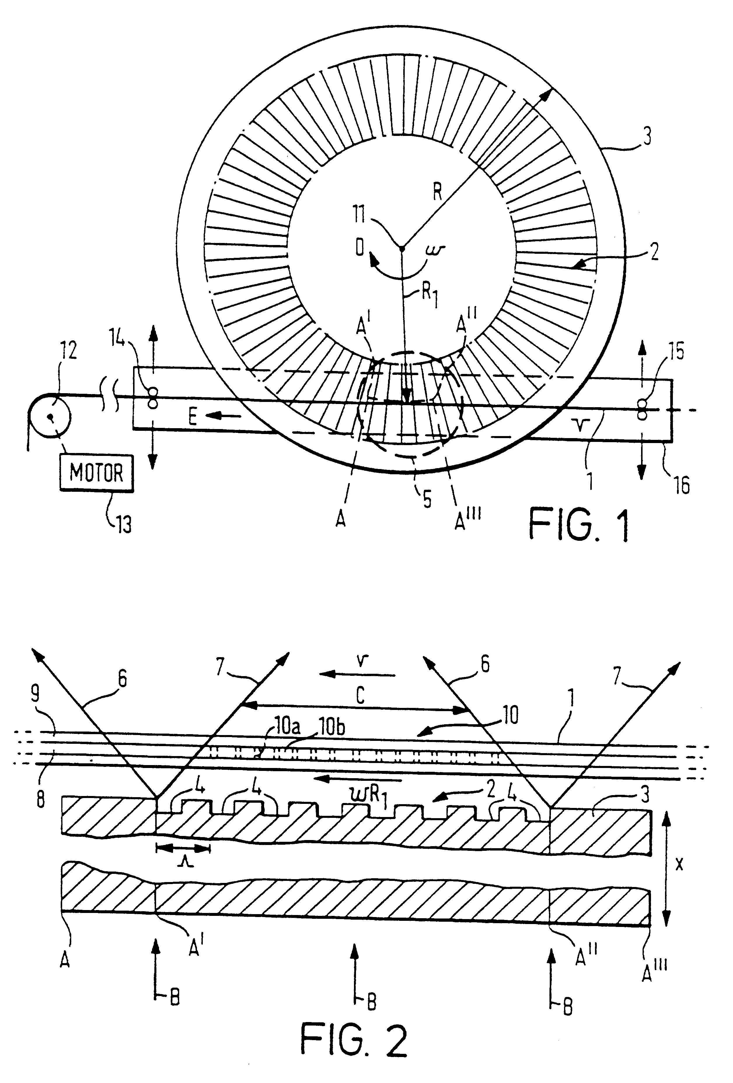
The plate 23 is overlaid by a phase mask 2 recorded in a glass plate 24. The phase mask is formed in the same way as the mask 2 shown in FIGS. 1 and 2. However, the plate 24 does not rotate. The centre 11 of the pattern 2 is arranged coaxially with the centre X of the spiral waveguide pattern on plate 23. The laser 21 is mounted on means (not shown) so as to move in a circular path 25 concentric with the circular pattern 2 of the phase mask. The beam B from the laser illuminates the phase mask and accordingly recor...
fifth embodiment
the invention is shown in FIG. 7, in which a planar phase mask 26 is used, aligned with a length of an optical fibre 1. In order to record the grating in the waveguide, the beam B of the laser 21 is scanned longitudinally of the length of the phase mask 26, in the direction of arrows E-E'. The fibre is held at each end of the phase mask by means of clamps 27, 28 that include piezo electric elements that may be driven by an electrical oscillating source 29, which causes the fibre to be stretched and relaxed longitudinally in an oscillatory manner, which is relatively rapid compared to the rate of scanning of the beam B. The cyclic stretching and relaxing of the fibre 1 results in apodisation of the recorded pattern and for further details, reference is directed to our PCT / GB96 / 03079 filed on Dec. 12, 1996.
The apparatus shown in FIG. 7 can be used to record a series of component refractive index grating patterns which are substantially contiguous, along the length of the fibre 1. Thus...
PUM
 Abstract
Description
Claims
Application Information
 - R&D
- Intellectual Property
- Life Sciences
- Materials
- Tech Scout
- Unparalleled Data Quality
- Higher Quality Content
- 60% Fewer Hallucinations
Browse by: Latest US Patents, China's latest patents, Technical Efficacy Thesaurus, Application Domain, Technology Topic, Popular Technical Reports.
© 2025 PatSnap. All rights reserved.Legal|Privacy policy|Modern Slavery Act Transparency Statement|Sitemap|About US| Contact US: help@patsnap.com


