Optical subscriber network system

a technology of optical subscriber network and optical subscriber, which is applied in the direction of transmission monitoring, multiplex communication, fault recovery arrangements, etc., can solve the problems of affecting the maintenance of the station, communication can be obstructed and interrupted, and the communication between the station and the faulted optical subscriber unit is completely broken

Inactive Publication Date: 2001-09-11
FUJITSU LTD
View PDF5 Cites 45 Cited by
  • Summary
  • Abstract
  • Description
  • Claims
  • Application Information

AI Technical Summary

Problems solved by technology

Therefore, if a fault occurs in the optical transmission-reception portion (transceiver system) of the optical network unit ONU, the communication between the station and the faulted optical network unit ONU will be completely broken.
Eventually the communication can be obstructed and interrupted.
Moreover, the maintenance in the station is relatively easy while it is difficult to specify whether the faulted point resides in the transmission line or in the optical network unit because information of the optical network unit is not obtained at the side upon the fault.
Therefore, fieldworks increase so that restoration time, material and human costs grow to remove the fault of the optical network unit.
This system must follow a great cost increase.
When the active system has a fault, a switchover is made to the standby system, thereby improving faultiness between the optical service unit and the optical network units.

Method used


Image

  • Optical subscriber network system
  • Optical subscriber network system
  • Optical subscriber network system

Examples


Embodiment Construction

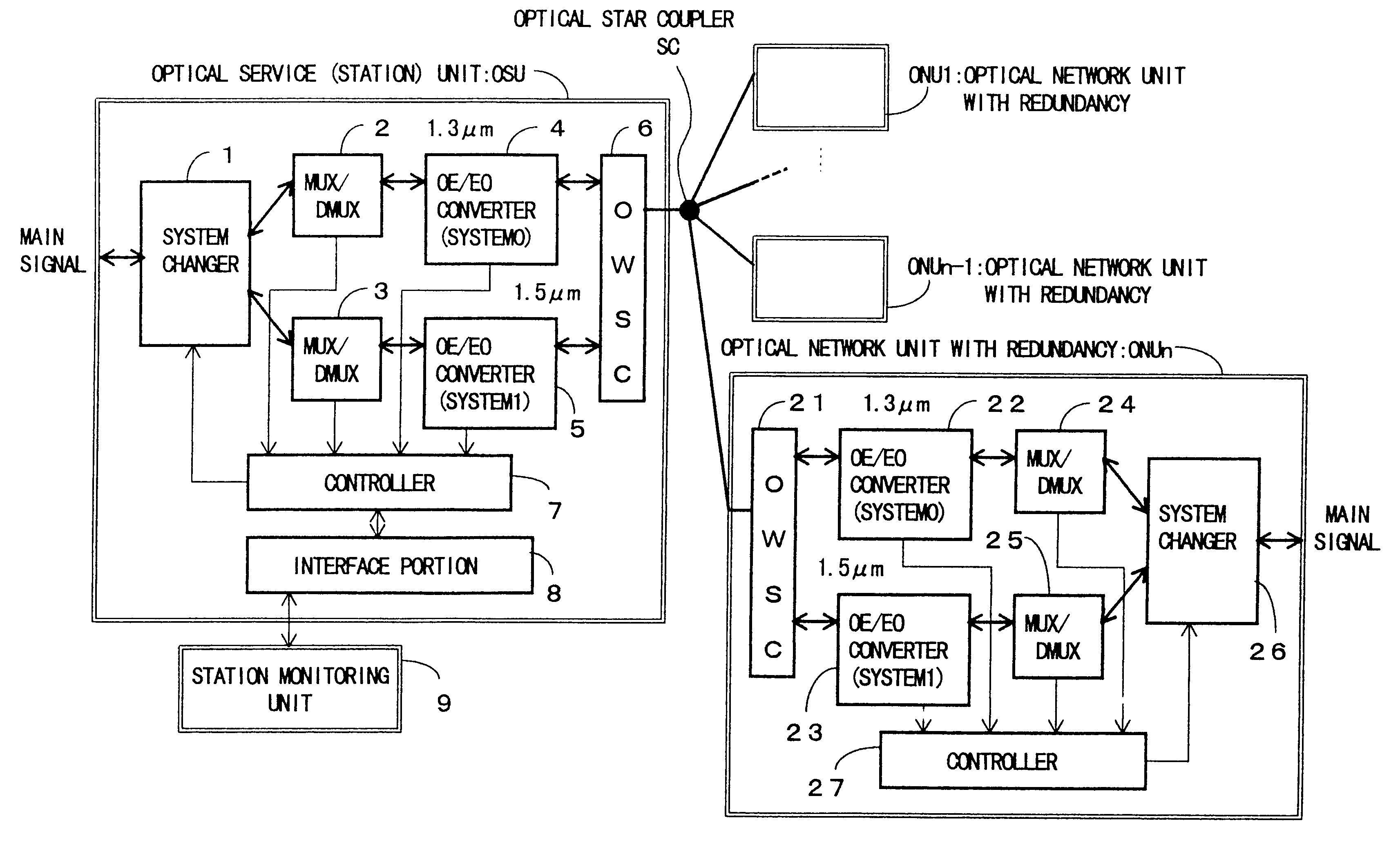
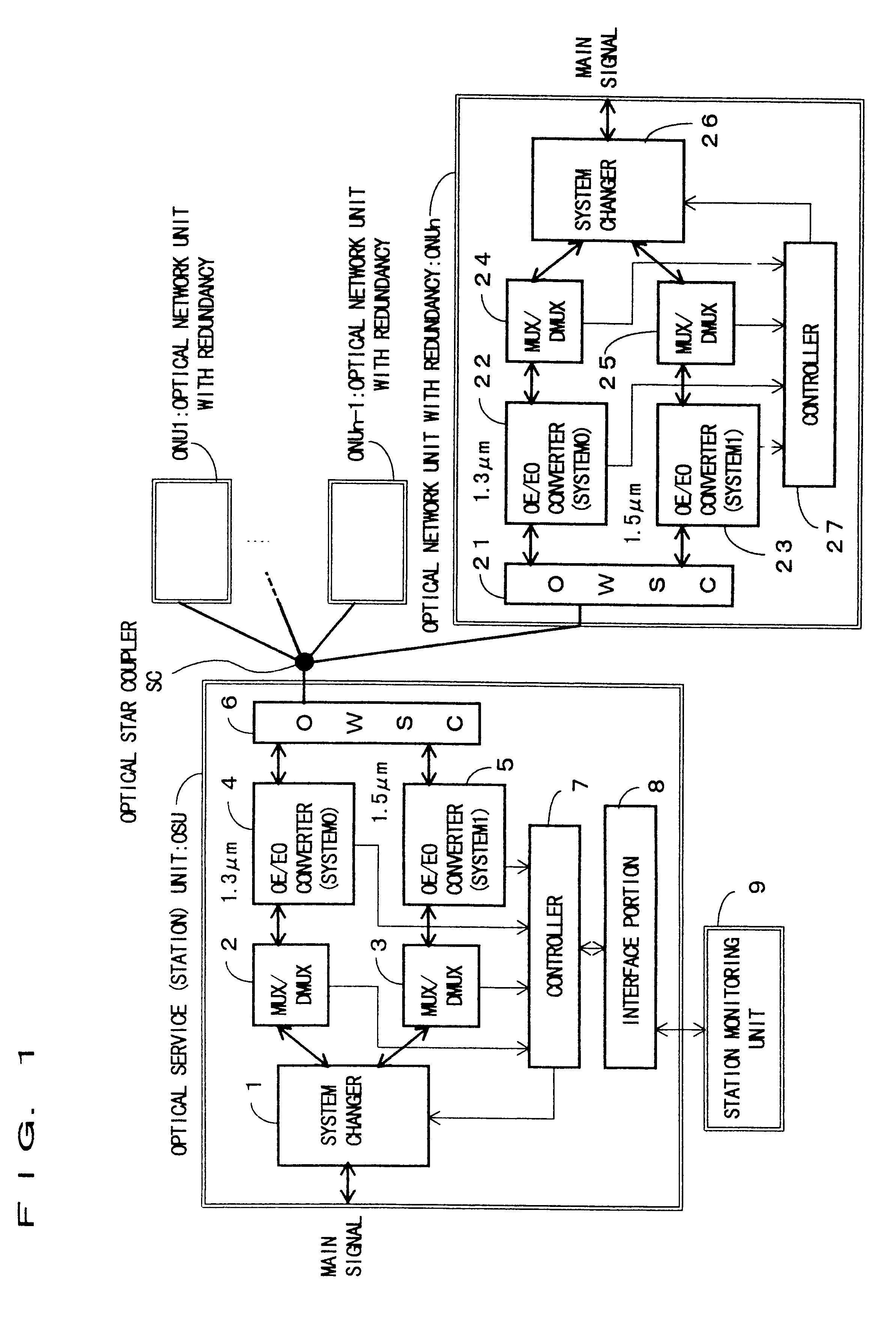
FIG. 1 shows an embodiment (1) of an optical subscriber network system according to the present invention. An optical service unit (station unit) OSU and optical network units (subscriber units) ONU1-ONUn have respectively duplexed (dual) optical transmission systems which communicate between the station-the subscribers by TDMA / TCM multiplexing method with the optical wavelengths of 1.3 .mu.m (system0) and 1.5 .mu.m (system1).

Namely, the optical service unit OSU is composed of a system changer 1, a multiplexing / demultiplexing (MUX / DMUX) portion 2 of the system0, a multiplexing / demultiplexing portion 3 of the system1, photoelectric (OE / EO) converters 4, 5 of the system0, an optical wavelength selecting coupler 6, a controller 7, and an interface portion 8. The system changer 1 separates an electrical main signal into the system1 and system2. The multiplexing / demultiplexing portion 2 of the system0 and the multiplexing / demultiplexing portion 3 of the system1 multiplex a main signal fr...


PUM


Abstract

In an optical subscriber network system which connects plural optical network units to an optical service unit using passive optical elements through an optical transmission line, the optical transmission line is duplexed with a lower cost. The optical service unit and the optical network units each have plural transmission-reception portions the wavelengths of which are different from each other, and the inputs and outputs of the plural transmission-reception portions are multiplexed with the wavelengths (WDM) into a single optical transmission line to form a pseudo redundant communication path between the optical service unit and the optical network units. The communication which uses a certain wavelength between the optical service unit and the optical network units is active, and the communication which uses another wavelength is a standby. When the active communication has a fault, a switchover operation to the standby communication is performed. The communication path using plural wavelengths between the optical service unit and the optical network units can select either the function of "with redundancy" or "without redundancy" or "enhanced line speed", depending on subscribers' demands.

Description

1. Field of the InventionThe present invention relates to a light or optical subscriber network system, and in particular to an optical subscriber network system which is formed of a passive optical network.2. Description of the Related ArtTo subscribers requiring a high-speed and large capacity of communication, as shown in FIG. 12, has generally known a network system which accommodates optical subscribers #1-#n with optical network units generally designated by ONU through optical fibers generally designated by OF correspondingly constructed from an optical service unit (station unit) OSU in a station ST which is formed of the optical service unit OSU and a switchboard EX.On the other hand, in recent years, a passive optical subscriber network system as shown in FIG. 13 has been put into practice which accommodates optical subscribers which need a broad-band communication.This passive optical subscriber network system has an optical star coupler SC which consists of passive eleme...

Claims


Application Information

Patent Timeline
Patent Type & Authority Patents(United States)
IPC IPC(8): H04B10/207H04J3/16H04Q11/00H04B10/032H04B10/07H04B10/03H04B10/27H04B10/272H04J3/00
CPCH04J3/1694H04J14/0282H04J14/0297H04Q11/0062H04J14/0293H04Q2011/0083H04Q11/0067H04Q11/0071H04Q2011/0081
Inventor TOUMA, EISAKUSAKATA, TAKASHI
Owner FUJITSU LTD
Why Eureka
Try Eureka