
Apparatus and method for improving dynamic range in a receiver

a receiver and dynamic range technology, applied in the field of communication systems, can solve the problems of limiting the dynamic range of the homodyne receiver, affecting the dynamic range of the receiver,

Inactive Publication Date: 2001-09-11
CUBIC COMM
View PDF9 Cites 57 Cited by
  • Summary
  • Abstract
  • Description
  • Claims
  • Application Information

AI Technical Summary

Problems solved by technology

As a result, receivers using this topology typically exhibit LOs with substantially higher phase noise for carrier frequencies at the lower end of the tuning range of the receiver than other architectures.
Homodyne receivers are limited, however, in dynamic range.
Non-ideal characteristics of circuits such as the mixers, quadrature splitters and other circuits result in self interference with the homodyne receiver.
These methods are limited, however, in that the DC (direct current) signal produced by the homodyne architecture can not be eliminated unless the modulated signal has a zero mean.
The dynamic range, therefore, of the receiver is limited.
Therefore, the schemes are further limited in their ability to correct deficiencies quickly.

Method used


Image

  • Apparatus and method for improving dynamic range in a receiver
  • Apparatus and method for improving dynamic range in a receiver
  • Apparatus and method for improving dynamic range in a receiver

Examples


Embodiment Construction

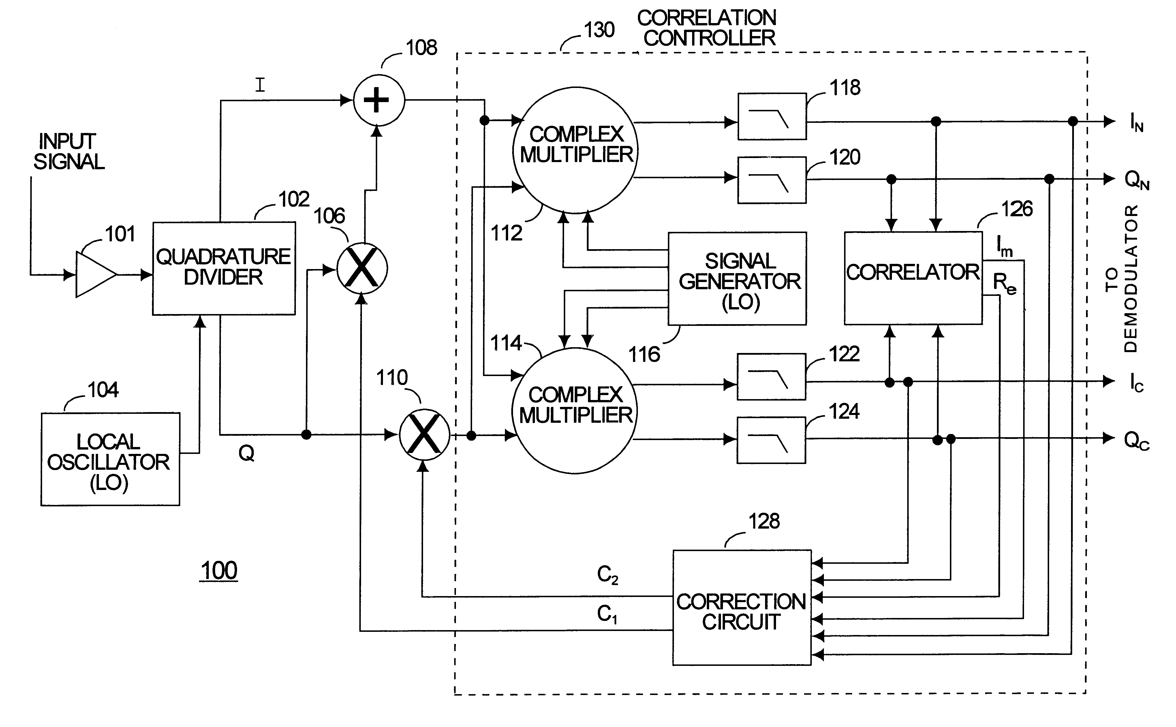
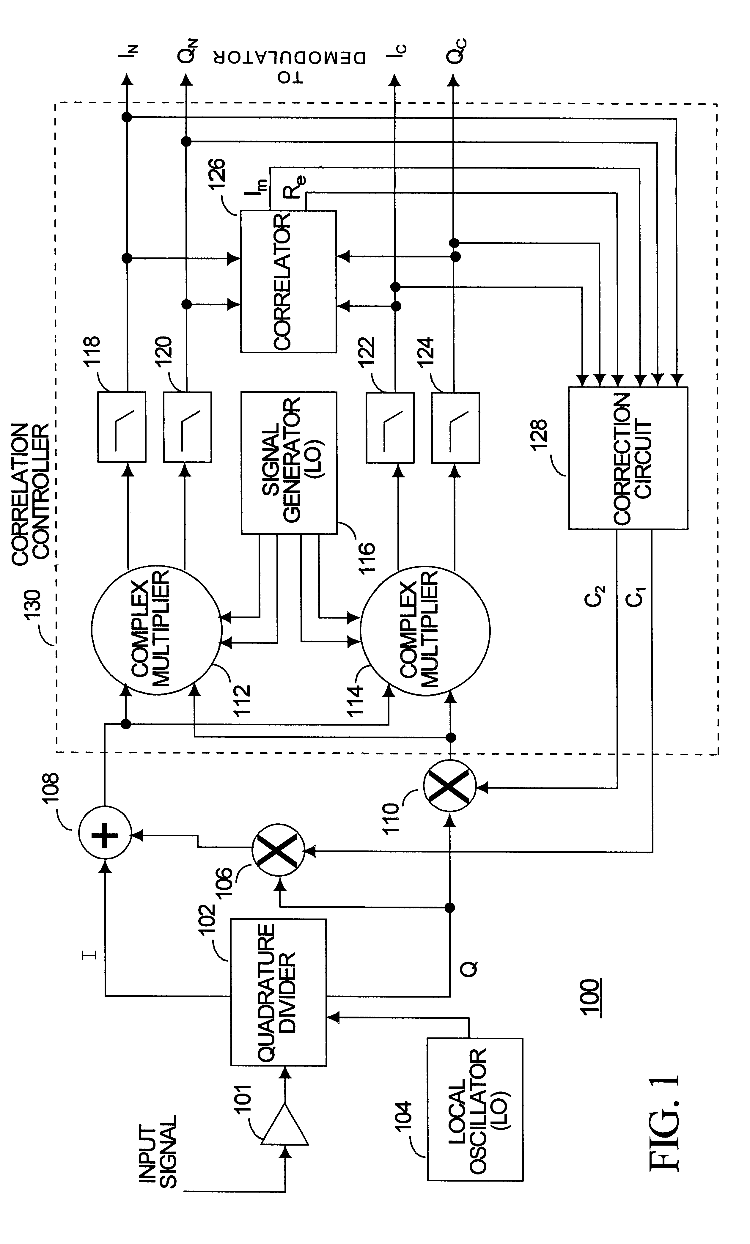
FIG. 1 is a block diagram of a low IF receiver 100 in accordance with a preferred embodiment of the present invention. Although in the preferred embodiment, the receiver 100 is part of a wireless radio frequency communications system, the present invention may be used in a variety of wireless and wired communication systems such as satellite, cellular telephone, cordless telephone, cable telephony, radar, microwave, infrared, and optical communication systems.

An incoming input signal at a carrier frequency (fc) is received at the receiver 100, preferably, through an antenna. An amplifier 101 amplifies the input signal to maximize the SNR during processing. The input signal is divided into two signals (two channels) and frequency shifted to an intermediate frequency (IF) in the quadrature divider 102. A local oscillator 104 generates an LO signal at the LO frequency that is mixed with the incoming signal to shift the incoming signal to the IF. Therefore, in the preferred embodiment, ...


PUM


Abstract

Phase errors and gain errors are reduced in a receiver to increase the dynamic range of the receiver. An input signal is shifted to an intermediate frequency (IF) and divided into a first channel and a second channel. The first and second channels are multiplied by a complex intermediate frequency signal having a frequency equal to the negative of the IF and by the complex conjugate of the intermediate frequency signal to produce a complex normal signal and a complex conjugate signal. A gain correction factor and a phase correction factor are adjusted based on a correlation signal produced by multiplying the complex normal signal by the complex correlation signal.

Description

1. Field of the InventionThe present invention relates in general to communication systems and specifically to a method and apparatus for improving the dynamic range of a receiver.2. Description of the Related ArtPresently, various methods exist for receiving a radio signal. A popular method involves using a superheterodyne receiver. Superheterodyne receivers shift an incoming input signal to at least one intermediate frequency before producing the demodulated output signal. Filtering spurious signals and other unwanted signals can be accomplished more easily at the intermediate frequency (IF) than at baseband or at the carrier frequency at which the radio signal is transmitted. For receivers having a relatively small tuning range relative to the lowest carrier signal that is to be received, the IF is typically lower than the lowest carrier frequency and is chosen to minimize unwanted spurious signals.Receivers having a wide tuning range (where the highest carrier frequency is many ...

Claims


Application Information

Patent Timeline
Patent Type & Authority Patents(United States)
IPC IPC(8): H04B1/12H04B1/10H04L27/00
CPCH04B1/109H04B1/123H04L2027/0016G01S7/4021G01S7/2886G01S7/358
Inventor RICHARDS, WAYNE E.JEKEL, RICHARD NEWELL
Owner CUBIC COMM
Learn More