Dielectric-patch resonator antenna

a technology of patch resonator and dielectric resonator, which is applied in the direction of resonant antenna, substantially flat resonant elements, and radiating elements of protection materials, etc., can solve the problems of large size, limited bandwidth and large size of antennas, and antennas that also exhibit significant reduction in gain

Inactive Publication Date: 2001-09-18
QUALCOMM INC
View PDF17 Cites 59 Cited by
  • Summary
  • Abstract
  • Description
  • Claims
  • Application Information

AI Technical Summary

Problems solved by technology

These antennas, however, have several disadvantages, such as limited bandwidth and large size.
These antennas also exhibit a significant reduction in gain at lower elevation angles (for example, around 10 degrees), which makes them undesirable for use in satellite phones where a given satellite used for communication may frequently be near this low elevation.
Another issue facing many wireless device designers is the use of or proposal to incorporate GPS capabilities in such devices as an added feature.
Therefore, implementing GPS related signal processing and services necessitates an additional antenna and consumes extra room to position the additional GPS antenna within the device.
While GPS can utilize a relatively small patch antenna element, it is still an inconvenience to manufacture a device with a completely separate antenna element.
It is also very difficult and sometimes commercially impractical to allocate such extra space and position the patch in a manner that operation is not inhibited by other components within the wireless device, without making the device unacceptably bulky, or non-asthetic, not to mention dramatically more expensive.
Size is considered a very large henderance to marketability.
In some applications such as in the case of mobile satellite phones, any increase in size a

Method used


Image

  • Dielectric-patch resonator antenna
  • Dielectric-patch resonator antenna
  • Dielectric-patch resonator antenna

Examples


Embodiment Construction

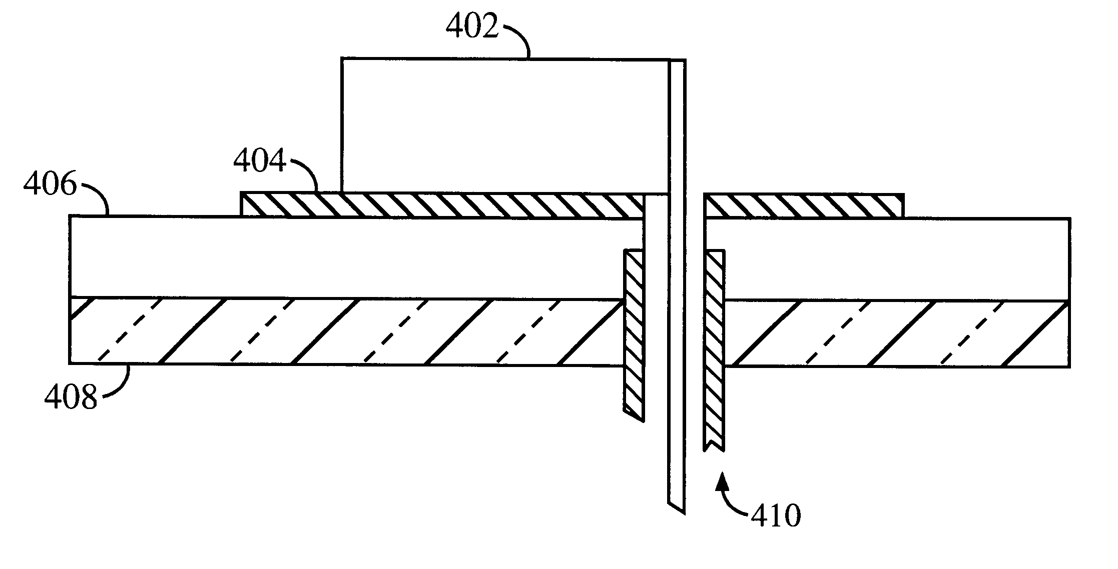
The dielectric resonator and stacked antenna designs discussed above are improvements over the art, providing: low profile, small-sized antennas for satellite communication applications, with simplified attachment to a PCB feed and for mounting elements such as power amplifiers and so forth. This arrangement allows for integration of other antenna types along the dielectric resonator antenna axis , thereby allowing for multifunction, multi-band performance in a single low profile assembly.

However, there also exist other antenna applications that do not rely on the more precise circularly polarized signal designs for assuring efficient or lower loss signal reception, but that can use a simple patch type antenna. One such application is the use of the Global Positioning System (GPS) to obtain accurate position location information for a wireless device user. There are many new proposed services being offered to prospective wireless device users , such as in the field of mobile telepho...


PUM


Abstract

A dielectric-patch resonator antenna having a resonator formed from a dielectric material mounted on a ground plane with a conductive skirt, and a patch element disposed inbetween. The ground plane and patch are formed from conductive materials. First and second probes are electrically coupled to the resonator for providing first and second signals, respectively, to or receiving from the resonator. The first and second probes are spaced apart from each other. The first and second probes are formed of conductive strips that are electrically connected to the perimeter of the resonator and are substantially orthogonal with respect to the ground plane. A dual band antenna can be constructed by positioning and connecting two dielectric resonator antennas together. Each resonator in the dual band configuration resonates at a particular frequency, thereby providing dual band operation. The resonators can be positioned either side by side or vertically.

Description

I. Field of the InventionThe present invention relates generally to antennas for wireless devices. More specifically, the present invention relates to a dielectric and patch resonator antenna assembly that uses a patch element disposed between a ground plane and a dielectric resonator to provide GPS signal reception.II. Description of the Related ArtRecent advances in wireless communication devices, such as mobile and fixed phones for use in satellite or cellular communications systems, have motivated efforts to design antennas more suitable for use with such devices. New antennas are generally needed to meet design constraints being imposed on new devices including overall size, profile, weight, and manufacturability. Several factors are usually considered in selecting an antenna design for a wireless device or phone, such as the size, the bandwidth, and the radiation pattern of the antenna.The radiation pattern of an antenna is a very significant factor to be considered in selecti...

Claims


Application Information

Patent Timeline
IPC IPC(8): H01Q5/01H01Q21/28H01Q1/40H01Q9/32H01Q1/00H01Q5/00H01Q21/00H01Q9/04H01Q5/10H01Q5/40
CPCH01Q1/40H01Q5/00H01Q9/0407H01Q5/40H01Q9/0485H01Q9/32H01Q21/28H01Q9/0414
Inventor LIM, BENG-TECK
Owner QUALCOMM INC
Why Eureka
Try Eureka