Receptacle for coaxial plug connector

a coaxial plug and connector technology, applied in the direction of coupling device details, coupling device connections, coupling protective earth/shielding arrangements, etc., can solve the problem of increasing manufacturing costs

Inactive Publication Date: 2001-10-02
MATSUSHITA ELECTRIC WORKS LTD
View PDF4 Cites 51 Cited by
  • Summary
  • Abstract
  • Description
  • Claims
  • Application Information

AI Technical Summary

Benefits of technology

In the preferred embodiment, the outer conductor shield is supported onto the peripheral wall of the mold to project the bottom of the socket into the cavity. Thus, the mold can absorb a fraction of the socket length required for receiving the plug connector, thereby minimizing the height of the receptacle.
The spring member is preferably formed by a single metal sheet to have the center electrode integrally struck therefrom and the movable contact bulged therefrom, simplifying the structure of the combination of the center electrode and the movable contact for reduced manufacturing cost.
In the preferred embodiment, the center electrode is of an L-shaped configuration to have a vertical leg extending along the axis of the socket and a contact tip extending horizontally from one end of the leg in a direction perpendicular to the axis of the socket for direct contact with the center conductor post of the coaxial plug connector. Further, the contact tip may have a return bent tab extending back into the center opening to reduce a gap between the contact tip and the periphery of the opening so as to prevent the clogging of a foreign matter which would impede the movement of the center electrode.
In the meanwhile, thus configured receptacle can be suitably combined with the coaxial plug connector having a compact structure. The plug connector includes a mount base adapted to be fixed to a mounting structure; and a coaxial plug having a longitudinal axis and supported to the mount base to project therefrom. The coaxial plug has an insertion end at one axial end thereof for mating connection with the receptacle and has an anchor end at the opposite axial end for connection with the coaxial cable. The outer conductor tube of the plug surrounds the center conductor post in an electrically insulating relation therefrom by means of a dielectric member fitted within the outer conductor tube. The dielectric member occupies a fraction of a space between the center conductor post and the outer conductor tube, thereby leaving an air layer extending along the length of the coaxial plug within the space. By provision of the air layer along the coaxial plug, the outer conductor tube can be spaced from the center conductor post by a reduced radial distance due to the large dielectric constant of the air layer, thereby making the plug and the complementary receptacle compact with respect to the radial dimension thereof.
The air layer can be realized by use of a specially configured dielectric member. For instance, the dielectric member is shaped into a barrel which surrounds the center conductor post and has rings spaced axially along the plug. The rings are held in close contact with the outer conductor tube to retain the barrel within the tube. The barrel has its outer surface spaced radially from the tube to leave the air layer extending along the plug between the axially spaced rings. Further, an additional air layer may be formed between the barrel and the center conductor post for minimizing the radial dimension of the plug.

Problems solved by technology

Further, the pin itself adds the number of discrete parts for assembly the receptacle, resulting in a manufacture cost increase.

Method used


Image

  • Receptacle for coaxial plug connector
  • Receptacle for coaxial plug connector
  • Receptacle for coaxial plug connector

Examples


Embodiment Construction

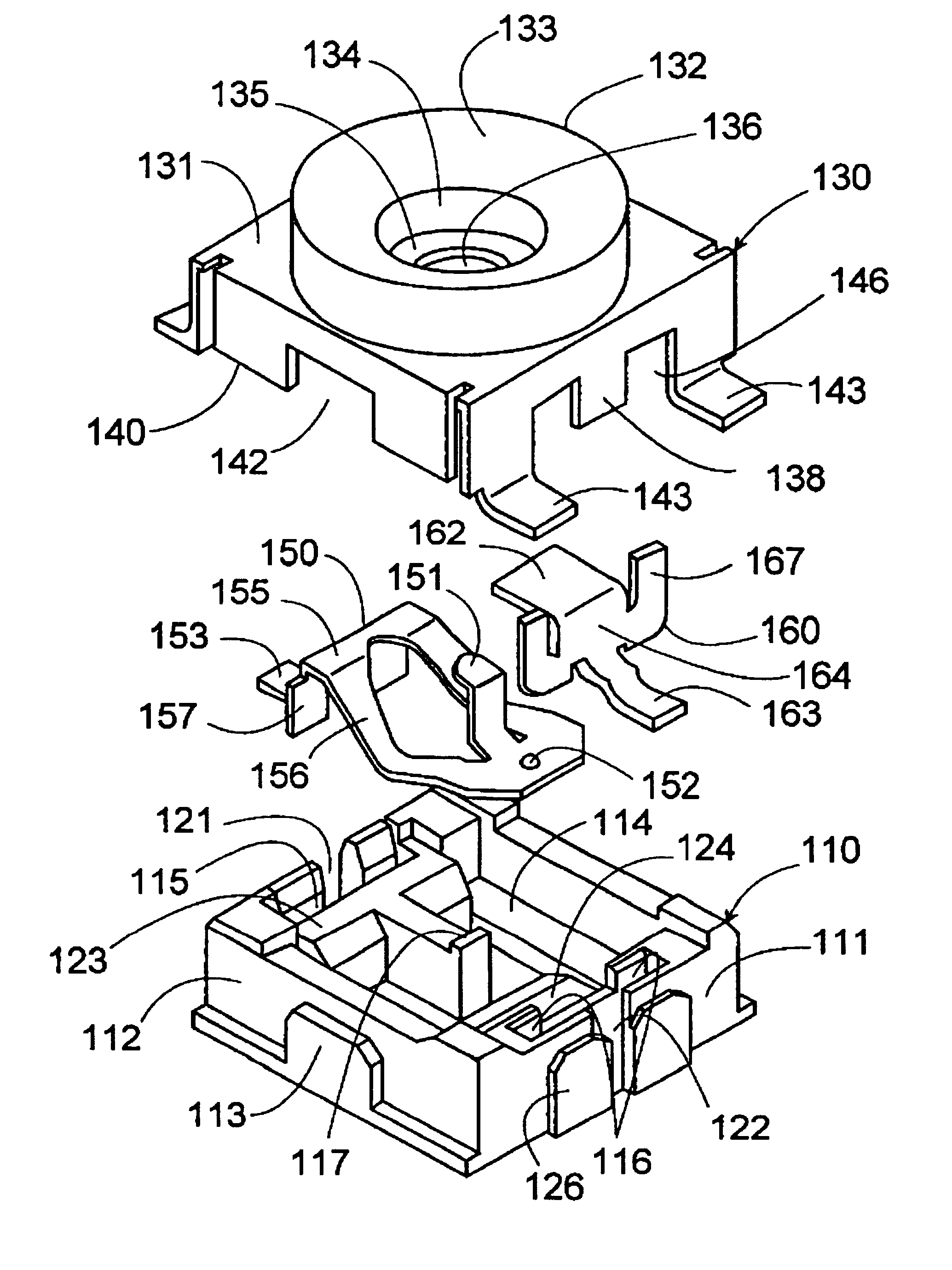
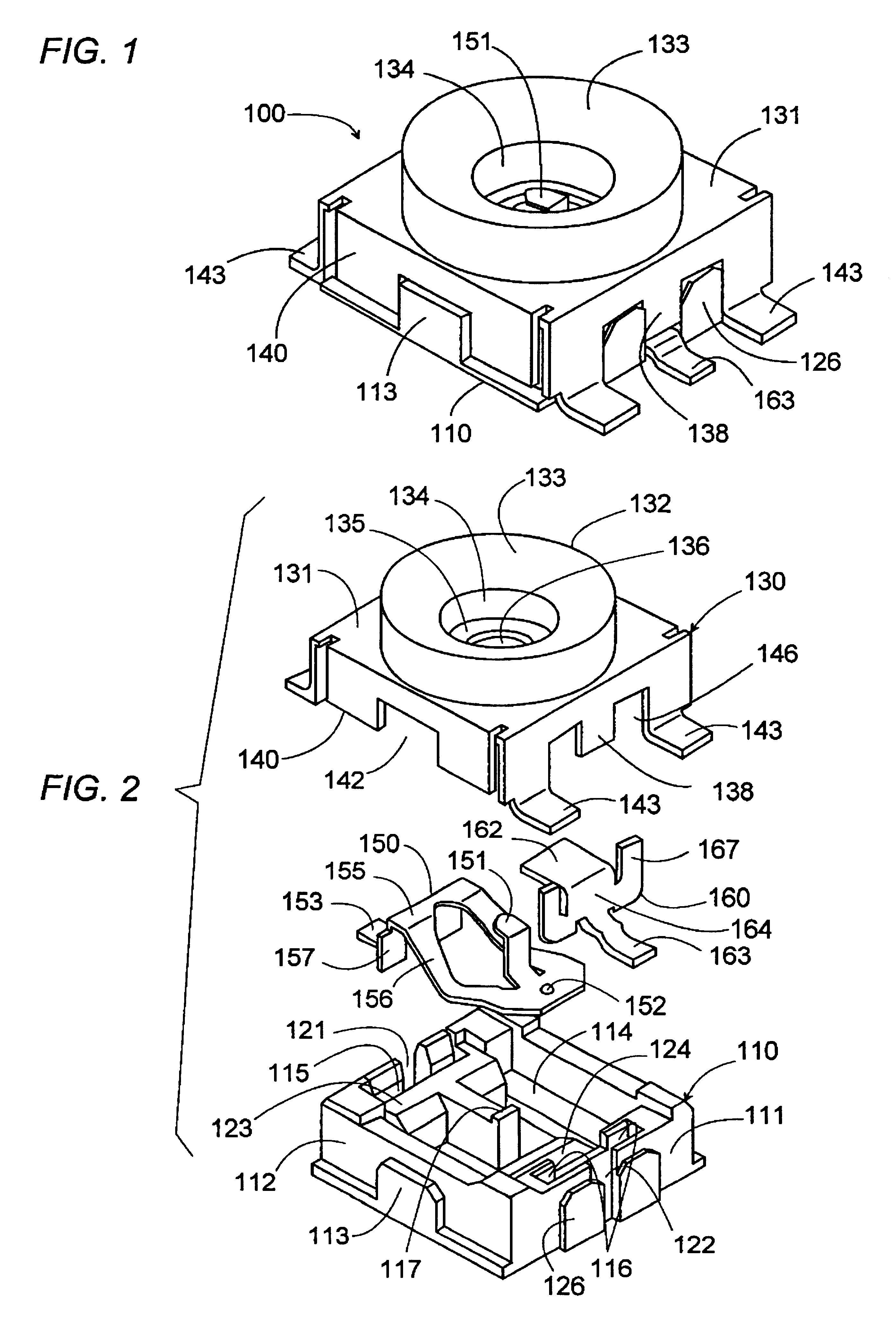
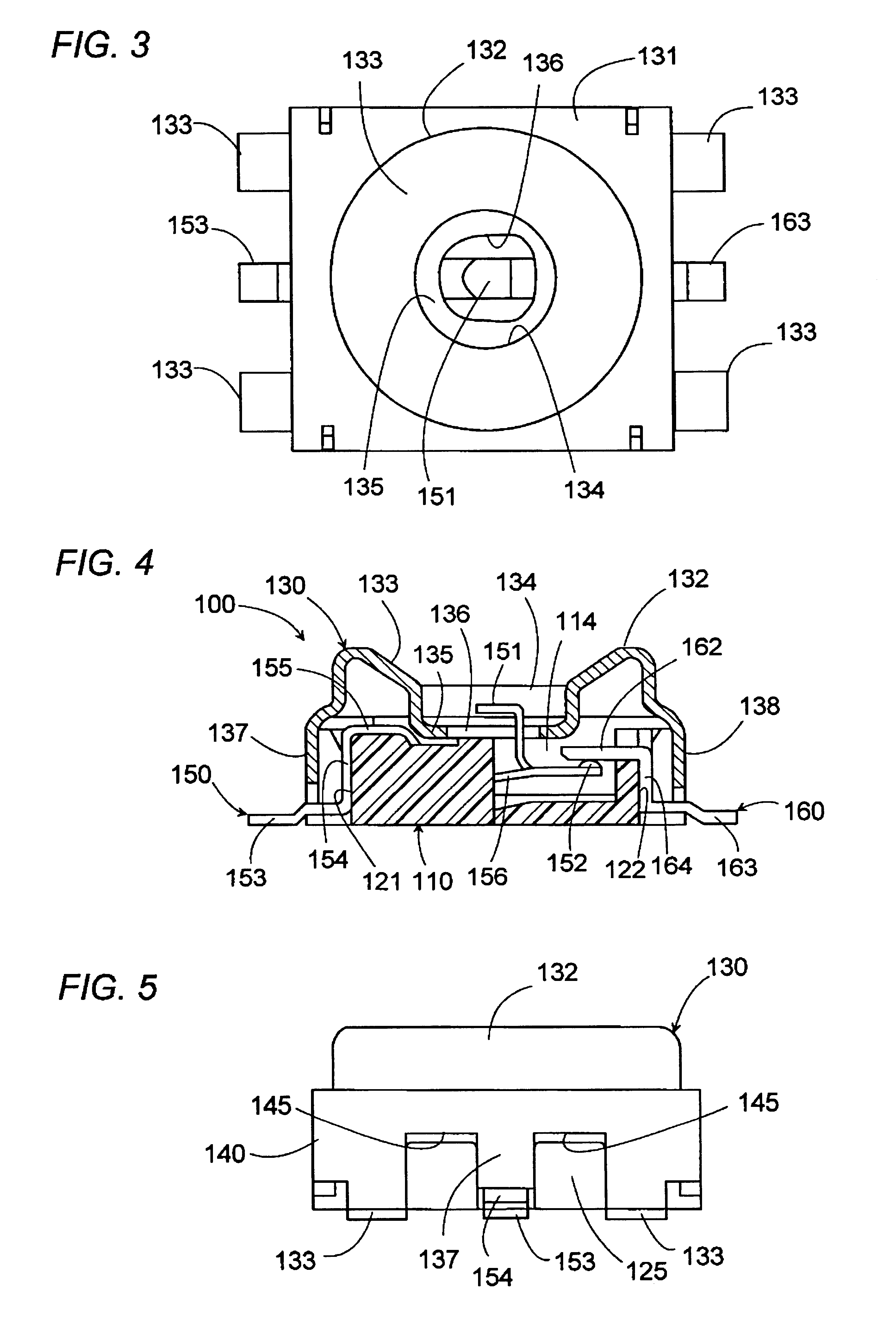
Referring now to FIGS. 1 to 5, there is shown a receptacle 100 adapted to receive a complementary coaxial plug connector 10 in accordance with a preferred embodiment of the present invention. The coaxial plug connector 10 is designed for connecting a coaxial cable 1 to the receptacle 100, and is specifically adapted for detachable connection of a mobile phone to a cradle carried on a vehicle for hands-free operation in driving. More particularly, the combination of the coaxial plug connector 10 and the receptacle is used to switch a signal line from a phone's internal antenna to a vehicles external antenna for increasing the antenna gain when the phone is operated in the vehicle. The receptacle 100 is mounted on a mobile phone casing 90, while the plug connector 100 is mounted on a cradle housing 190. The receptacle 100 is shaped into a low-profile configuration and is received within a hole 91 of the thin-wall mobile phone casing 90, as shown in FIGS. 6 and 7. The coaxial plug conn...


PUM


Abstract

A compact receptacle for mating connection with a complementary coaxial plug connector. The receptacle is in use to be mounted on a mobile phone for switching a signal line from an internal antenna to a vehicle's external antenna when placed on a cradle in a vehicle in mating connection with the plug connector on the cradle. The receptacle has a dielectric mold carrying an outer conductor shield fitted on top of the mold, a single spring member, and a single fixed contact member. The conductor shield includes an electrode socket for connection with an outer conductor tube of the plug. The spring member integrally carries a center electrode for connection with a center conductor post of the plug, and a movable contact which forms a normally-closed switch with a fixed contact on the fixed contact member for the above signal switching.

Description

1. Field of the InventionThe present invention is directed to a receptacle for a coaxial plug connector, and more particularly to such a receptacle of compact design.2. Description of the Prior ArtAs disclosed in WO 98 / 31078, a receptacle has been proposed in combination with a self-aligning coaxial plug connector to facilitate a one-touch connection, while compensating for misalignment of the plug and the receptacle. Particularly in the field of connecting a mobile phone to a cradle in a vehicle for switching a signal line from a phone's internal antenna to an external antenna installed on the vehicle, the receptacle on the side of the mobile phone is required to have a set of contacts for switching the signal line, in addition to a center electrode and an outer electrode respectively for connection with a center conductor post and an outer conductor tube of the plug connector. The above publication teaches the use of a pin as the center electrode projecting into a socket for recei...

Claims


Application Information

Patent Timeline
Patent Type & Authority Patents(United States)
IPC IPC(8): H01R13/74H01R13/00H01R13/631H01R13/646H01R13/648
CPCH01R13/6315H01R13/745H01R24/46H01R24/50H01R2103/00H01R2201/16H01R13/648
Inventor FUJIMOTO, MASAKIKATO, SHUJIOKURA, KENJIINABA, YOSHIHISAHASHIMOTO, TAKESHIHOSHINO, NARUTOSHITOMINAGA, HIROYUKISASAKI, SHINYA
Owner MATSUSHITA ELECTRIC WORKS LTD
Why Eureka
Try Eureka