Cardiac resuscitation device for percutaneous direct cardiac massage

a direct cardiac massage and cardiac resuscitation technology, applied in the field of cardiopulmonary resuscitation methods and equipment, can solve the problems of unreversible brain death, few physicians today are skilled in direct cardiac massage techniques, and rather gross trauma procedures

Inactive Publication Date: 2001-10-02
ZADINI FILIBERTO P +1
View PDF72 Cites 10 Cited by
  • Summary
  • Abstract
  • Description
  • Claims
  • Application Information

AI Technical Summary

Problems solved by technology

It is documented that a cardiac arrest results in irreversible brain death if a sufficient blood flow is not reestablished within a critical period of time from the moment of the cardiac arrest.
However, few physicians today are skilled in the technique of direct cardiac massage.
In addition to that, this technique is often characterized by many physicians as a rather grossly traumatic procedure, often seen as a desperate terminal attempt to resuscitate an arrested heart.
However, the larger the sharp three-sided trocar tip, the more likely are injuries to the heart, coronaries or surrounding organs.
Such blind advancement carries extremely high risk of puncturing and/or lacerating the heart, coronary vessels or the surrounding structures, with devastating consequences.
Prisk and Johnson's proposed position of blindly inserting the trocar between the sternum and the pericardial sac is, indeed, an extremely risky procedure; this space being very narrow, while it is virtually impossible to insert the trocar into the other designated position, i.e., within the pericardial sac, this space bcing only virtual, since the visceral and parietal pericardium are in contact, separated only by a thin film of pericardial fluid.
Furthermore, the device proposed by Prisk and Johnson lacks any mechanism for locating the position of the sharp tip of the trocar and lacks any safety mechanisms to prevent or avoid injuries, such as puncturing of the heart or coronary vessels.
Moreover, an inflatable bladder with a laterally flexible stem, as proposed by Prisk and Johnson, lacks the required stability for maintaining its central position to effectively compress the heart.
Also, the proposed inflatable-deflatable bladder has no guidance, thus lacking the ability to properly impress direction of the compressions toward the vertebral column, allowing the heart to be displaced during the phase of compression laterally to the column, and not maintaining the heart in position between the vertebral column and the sternum, as required for effective pumping and resulting in ineffective compression of the heart.
Given the individual variability in the size and depth of the thoracic cage, the device of Prisk and Johnson is inadequate in that it has no means to adapt to the various depths of the thoracic cavity and ignores the variability in the distance between the sternum and the vertebral column.
Finally, the method of insertion of the Prisk and Johnson bladder is a multistep manual procedure, which is necessarily time-consuming and conflicts with the need for a rapid institution of cardiopulmonary resuscitation.
Although a thoracotomy of such a reduced size is indeed an improvement over a traditional thoracotomy, because it is more expedite, still it is not the solution to the problem of entering the chest cavity safely to introduce means...

Method used


Image

  • Cardiac resuscitation device for percutaneous direct cardiac massage
  • Cardiac resuscitation device for percutaneous direct cardiac massage
  • Cardiac resuscitation device for percutaneous direct cardiac massage

Examples


embodiment i

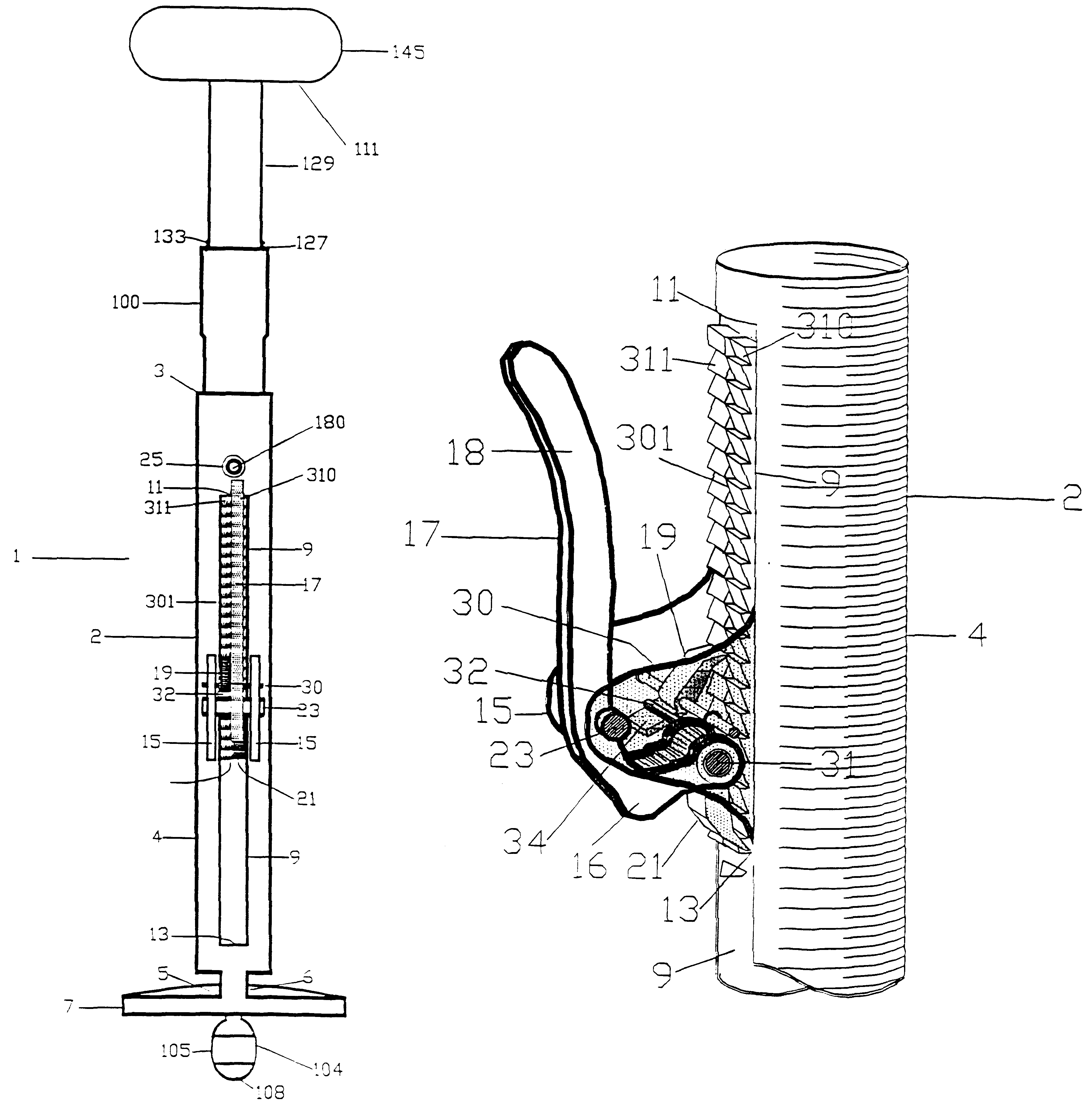
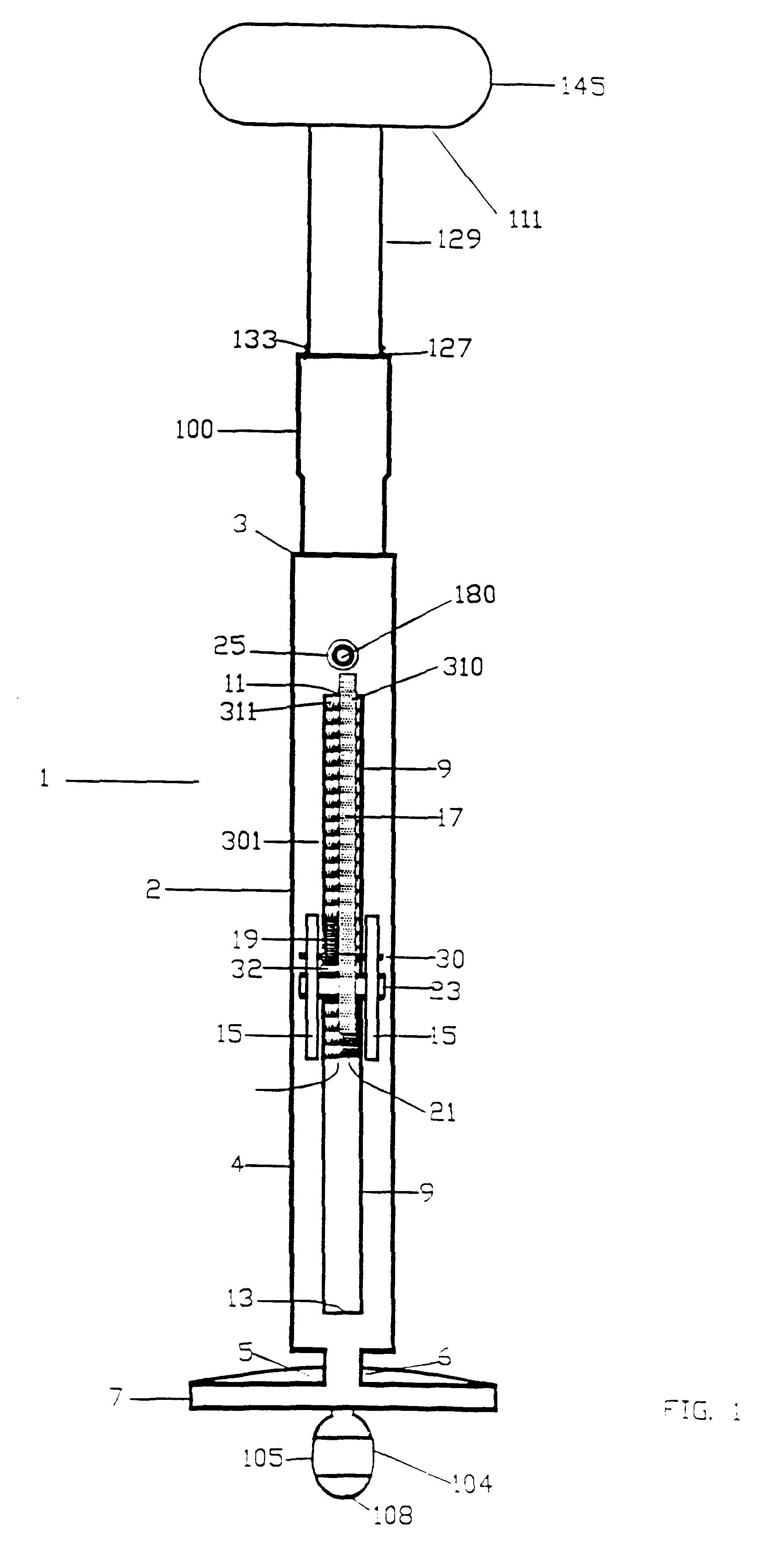
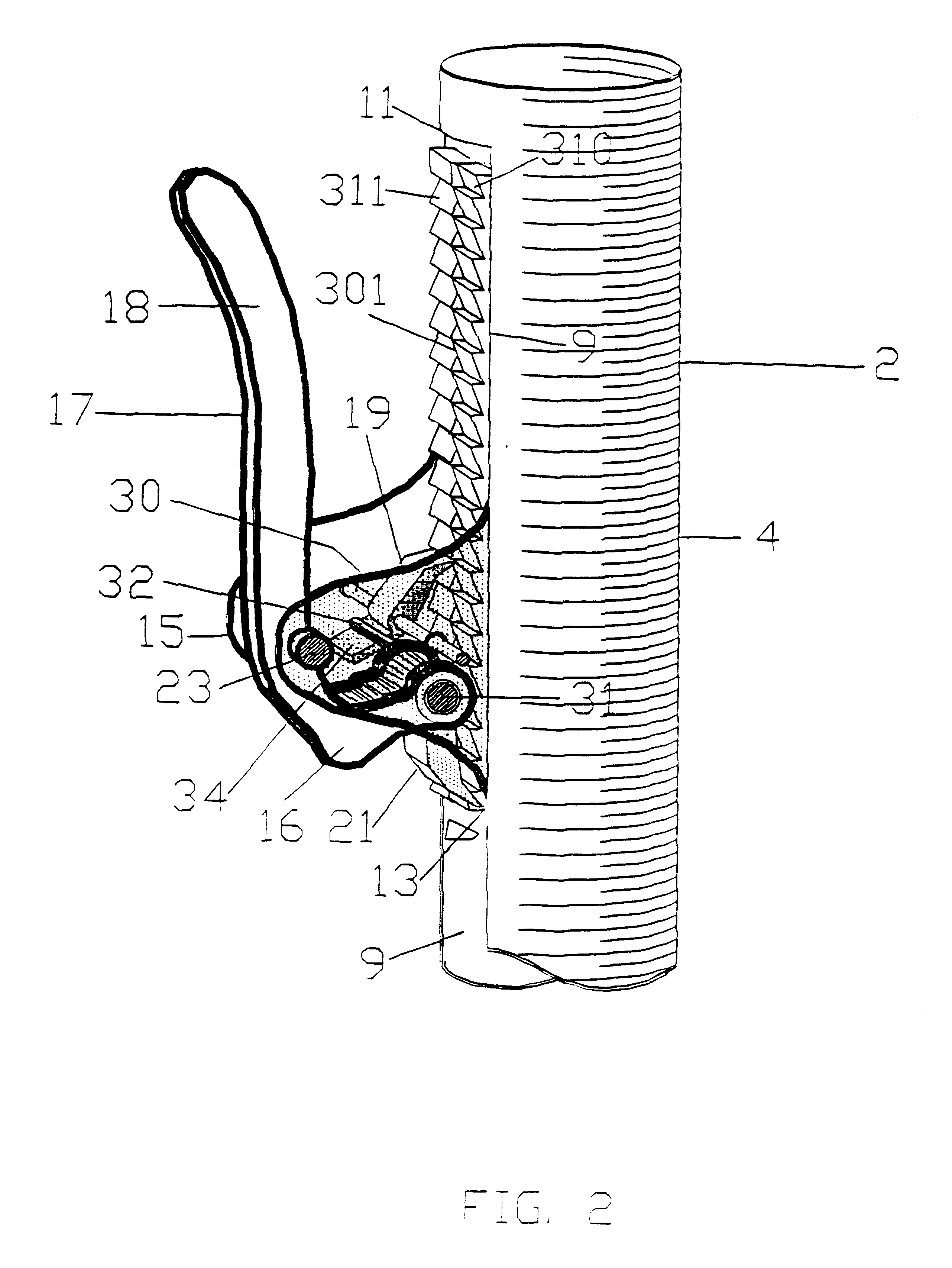
In that form of the present invention chosen for purposes of illustration in FIGS. 1-10, a percutaneous cardiac pump, indicated generally at 1, is shown with the actuating mechanism shown in the normal rest position. As best seen in FIG. 3, the cardiac pump 1 is composed of three main components, each of generally cylindrical shape and essentially coaxially mounted: an outer, generally cylindrical, component or support case, indicated generally at 2; an inner, generally cylindrical, component or stem member, or main unit, or stem unit, indicated generally at 100; and an intermediate member, also of generally cylindrical shape, indicated generally at 300, interposed between the stem member 100 and the support case 2.

The support case 2 is hollow and is of generally tubular, cylindrical shape having an open proximal end 3, a body 4 and a distal end 5, including a narrow neck 6, and a flat, circular base 7. The base 7 is preferably formed of transparent material to enable the operator t...

embodiment vi

Embodiment VI has numerous similarities and numerous parts which are identical to device 1250 of FIGS. 28 and 29. Reference numbers illustrating the same parts have been therefore maintained. FIGS. 30, 31, and 32, show an embodiment, indicated generally at 1200, of the cardiac pump 1 of FIGS. 1 to 10. The device includes a different type of expandable member carried by the blunt stem tip of a stem member.

As shown in FIG. 30, the device, generally indicated at 1200, is composed of two main components, stem member 1202 and expandable member 1204. Stem member 1202, of general cylindrical shape, comprises hollow stem 1203 having a proximal end 1205 and a distal end or stem tip 1201. Proximal end 1205 of stem member 1202, of general cylindrical shape as hollow stem 1203 but of larger diameter, is mounted in slideable fashion within recess 1207 of handle 1206. Spring or resilient means 1208 urges downward stem member 1202 Circular lid or arrest 1209 in handle 1206 does not permit exit of ...

embodiment vii

FIGS. 33 and 34 show vet an alternative form of device 1 of FIGS. 1 to 10. FIG. 33 is a cross-sectional view of the device generally indicated at 1300. Device 1300 is composed of two main components stem member 1302 and expandable member 1304. Stem member 1302 is composed of proximal end 1303, shaft 1305 and stem end 1306. Stem shaft 1305 is composed of three concentric cylindrical stems, outer 1308, intermediate 1309 and inner 1310. Stem member 1302 is provided proximally with handle 1206 in all similar to the two previously described device 1200 and 1250. Within handle 1206 recess 1207 of handle 1206 is slidably mounted proximal end 1205 of upper stem member segment 1310. Proximal end 1205 of upper stem segment 1310 is of general cylindrical shape as upper segment of stem member 1302 but of larger diameter. Spring or resilient means 1208 urges downward stem member 1302. Circular lid or arrest 1209 in handle 1206 does not pennit the exit of stem member 1302 from handle 1206 via eng...


PUM


Abstract

An apparatus and method for cardiac resuscitation wherein the apparatus has an expandable member carried by a rigid stem and placeable inside the chest cavity adjacent to the heart by the tip end of the stem to effect pumping of the heart by applying and releasing pressure to the expandable member via a rigid stem from outside the chest cavity through the chest wall so as to alternately compress and decompress the heart and further includes numerous safety mechanisms to prevent injuries to the intrathoracic organs and mishaps. Compression and decompression may be achieved by moving the expanded expandable member toward the heart and away from it, or by alternatively expanding and contracting said expandable member to effect pumping of the heart.

Description

1. Field of the InventionThis invention relates to methods and apparatus for cardiopulmonary resuscitation and is particularly directed to improved methods and apparatus for performing direct heart massage.2. Description of the Background ArtIn order to resuscitate a patient victim of a cardiac arrest, it is necessary to provide an adequate artificial circulation of oxygenated blood to the vital organs by reestablishing the pumping function of the heart at values as close as possible to the physiological prearrest condition. Such a cardiac pumping function must be instituted at the earliest possible stage. It is documented that a cardiac arrest results in irreversible brain death if a sufficient blood flow is not reestablished within a critical period of time from the moment of the cardiac arrest. Such a period of time is measured ranging between four and six minutes.In order to reestablish the pumping function of the heart, two methods of cardiopulmonary resuscitation have been use...

Claims


Application Information

Patent Timeline
IPC IPC(8): A61B17/34A61B17/02A61M1/10A61B17/32A61B17/00A61M60/295A61M60/497
CPCA61B17/0218A61B17/3494A61M1/106A61M1/1068A61M1/1048A61B17/0281A61B2017/00557A61B2017/320044A61M1/1046A61M60/497A61M60/295
Inventor ZADINI, FILIBERTO P.ZADINI, GIORGIO C.
Owner ZADINI FILIBERTO P
Why Eureka
Try Eureka