Method and apparatus for a shoring wall

a technology of shoring wall and shoring beam, which is applied in the direction of shaft equipment, shaft lining, artificial islands, etc., can solve the problems of not being able to provide any vertically oriented support for soil reinforcing on mason 204 wale beams, and not being able to construct economical soil nail wall construction, etc., to achieve the effect of improving face stability

Inactive Publication Date: 2001-10-09
BYRNE R JOHN +1
View PDF26 Cites 54 Cited by
  • Summary
  • Abstract
  • Description
  • Claims
  • Application Information

AI Technical Summary

Benefits of technology

The retaining element system of the present invention is designed to improve face stability in poorer quality soils that are not suited to conventional soil nailing. A method for shoring a face of an excavation is provided that includes inserting a plurality of retaining elements substantially vertically into an earthen mass. The earthen mass can be any material or combination of materials, such as soil, clay or rock that requires excavation for the in

Problems solved by technology

When the stand-up time of vertical cuts at the face is limited, face stability problems do not allow economical soil nail wall construction.
These situations typically require alternative, more costly wall systems, such as soldier piles, sheet piles or tieback walls.
However, the wale beams of Mason '204 fail to provide any vertically oriented support for the soil reinforcing rods that extend back horizontally into the excavation.
However, Carey '583 fails to teach any method that is applicable to softer soils.
A problem with Kulchin '

Method used


Image

  • Method and apparatus for a shoring wall
  • Method and apparatus for a shoring wall
  • Method and apparatus for a shoring wall

Examples


Embodiment Construction

The invention provides a method and apparatus for a wall system that retains earthen material. The wall system is particularly suited to shoring below grade excavations of softer and less stable soils, gravels and sandy materials.

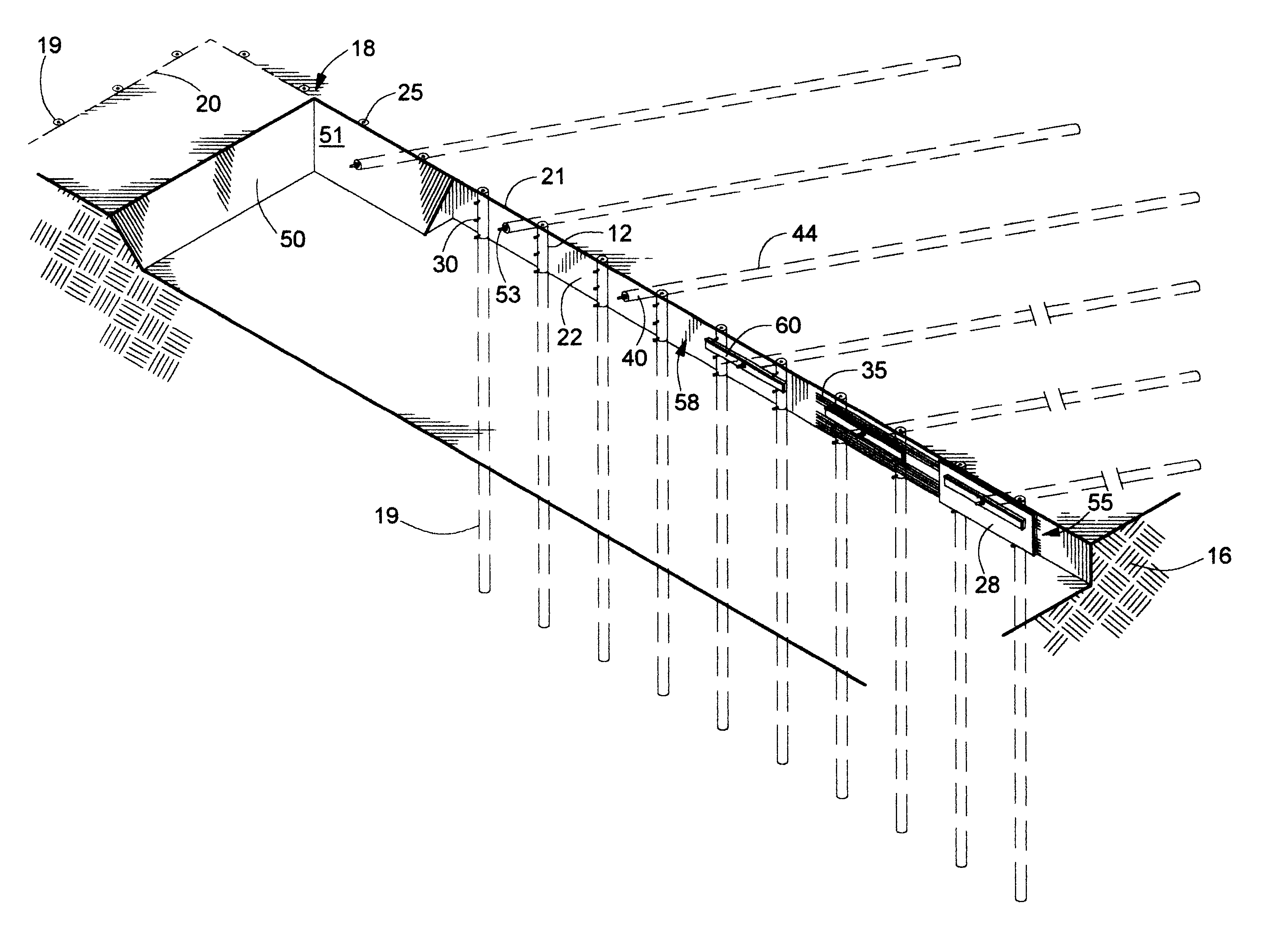
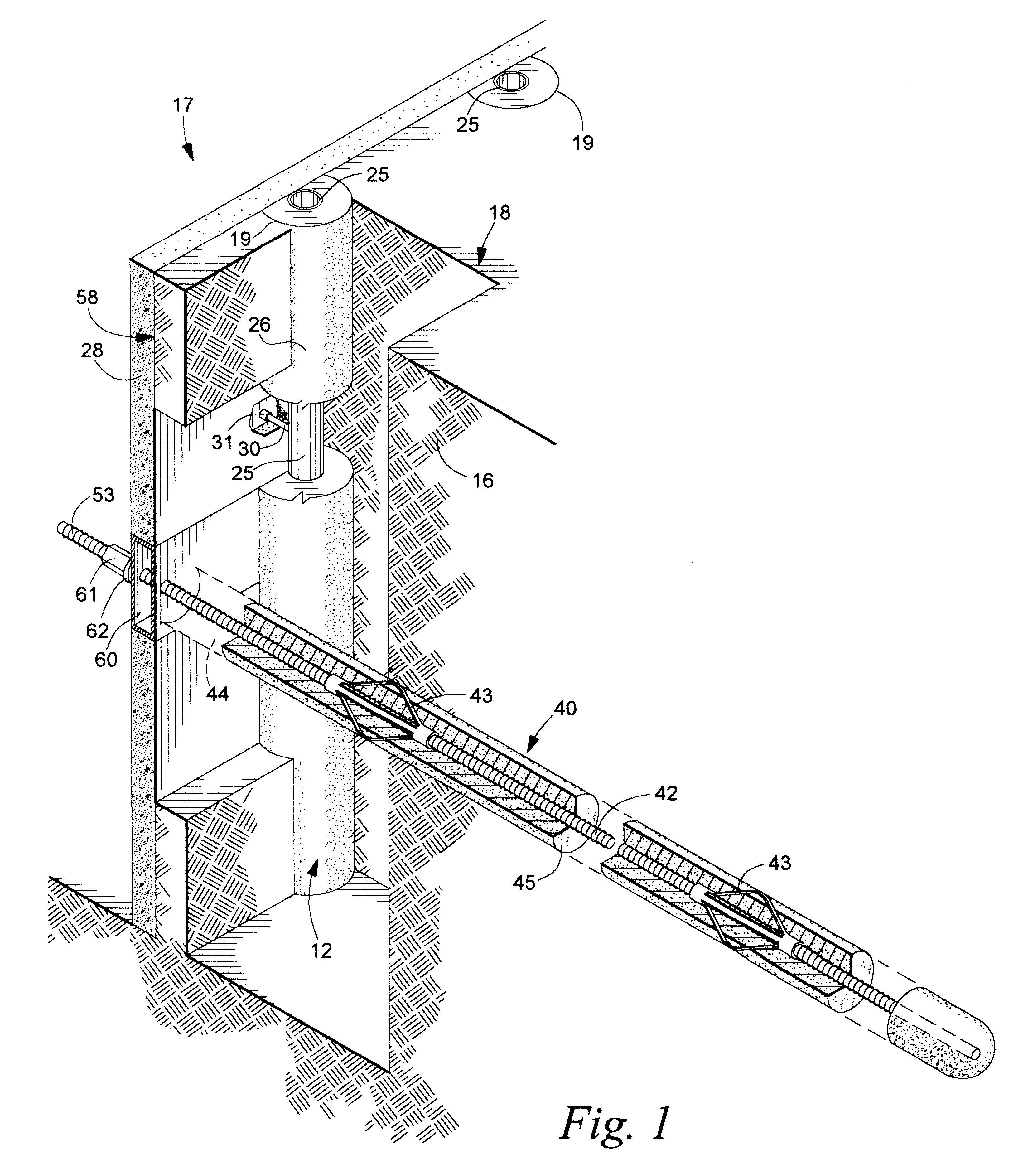
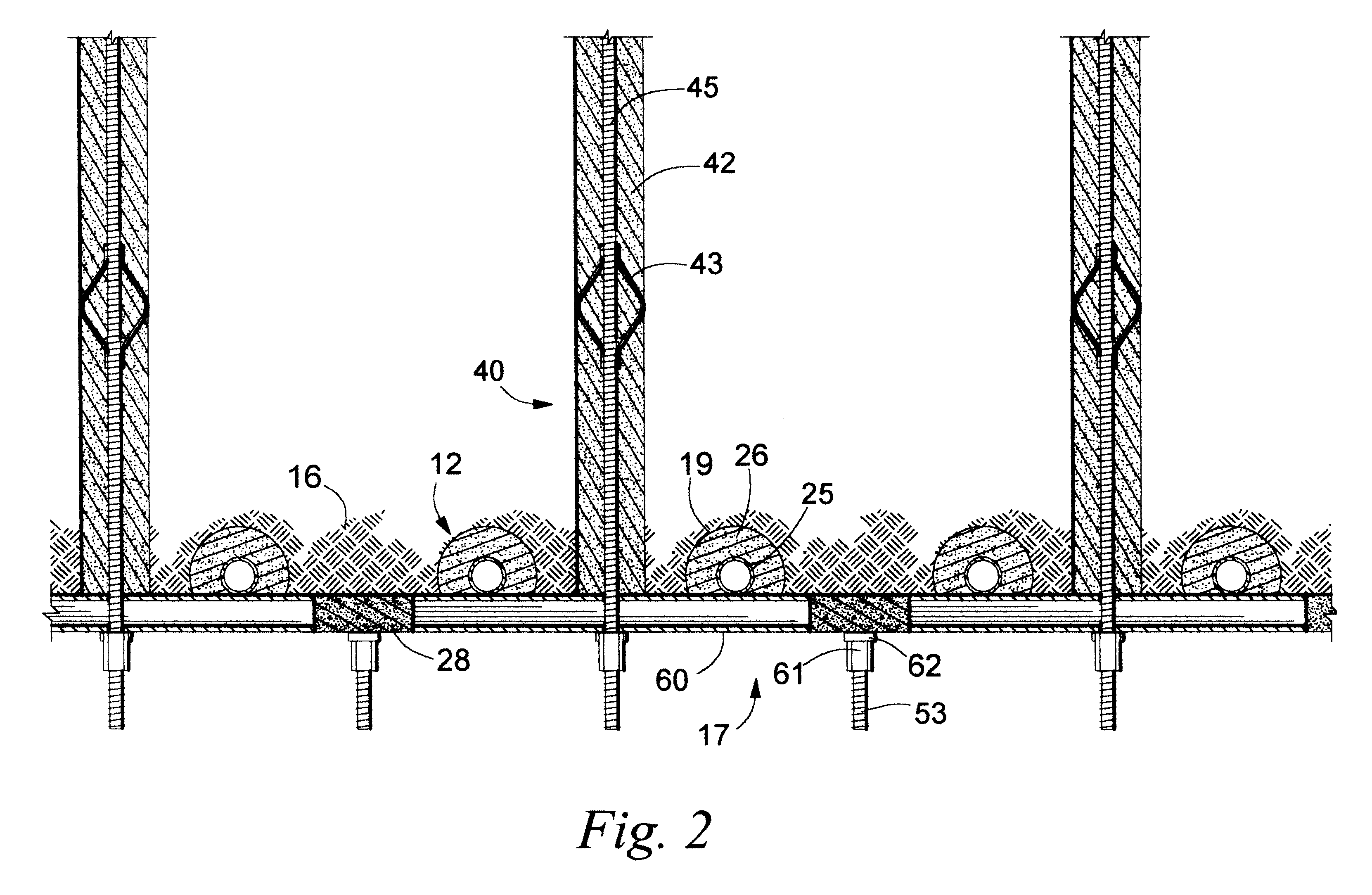
The method and apparatus for shoring a face of an excavation is shown in FIGS. 1 through 10. A preferred method comprises first inserting a plurality of retaining elements 12 into an earthen mass 16. The earthen mass can be any material or combination of earthen materials, such as soil, clay or rock that requires excavation for the installation of a shoring wall 17.

The earthen mass 16 includes a grade 18, which is the upper surface of the earthen mass. As detailed in FIG. 3, each of the retaining elements 12 are inserted into a bore hole 19 along a wall line 20, which runs along the grade at what will be the top edge 21 of the shoring wall. The retaining elements are inserted along the final wall line in a substantially vertical orientation to define an exc...


PUM


Abstract

A retaining element system is provided that improves face stability in poorer quality soils that are not suited to conventional soil nailing. The method includes inserting retaining elements substantially vertically into an earthen mass to shore the face of an excavation. The earthen mass can be any material or combination of materials, such as soil, clay or rock that requires excavation for the installation of a shoring wall. The plurality of retaining elements are placed side by side in a substantially linear arrangement. A plurality of soil nails are then inserted into the excavation plane, at the approximate midpoint between a pair of adjacent retaining elements. An exposed tip portion of each soil nail attaches to a wale, which is a substantially horizontal element that contacts a retaining element on both sides of each soil nail. The wale can be a beam, bracket, or a set of concrete reinforcement bars. The beam or bracket can either be a structural member, formed of steel or the like, or alternatively formed from a precast concrete. The concrete reinforcement bars can then receive a concrete fill to form a solid wale structure. Face stability is achieved with the pre-installed retaining elements, which with the wales provide complete facing support.

Description

The invention relates to a method and apparatus for a wall that retains earthen material, and more particularly to a shoring wall for below-grade excavations.Soil nailing is a cost-effective method of in situ ground reinforcement, in which passive, or non pre-stressed reinforcing elements are installed into the ground and attached to a facing of reinforced shotcrete or concrete. The cost effectiveness of soil nailing depends in part on the ability of vertical cuts in the ground to stand unsupported for a sufficient length of time to allow erection of the face reinforcing steel and subsequent application with shotcrete. The length of time that a vertical face can stand unsupported is referred to as "stand-up time." When the stand-up time of vertical cuts at the face is limited, face stability problems do not allow economical soil nail wall construction. These situations typically require alternative, more costly wall systems, such as soldier piles, sheet piles or tieback walls.U.S. P...

Claims


Application Information

Patent Timeline
IPC IPC(8): E02D5/76E02D5/74E02D5/80
CPCE02D5/74E02D5/76E02D5/808
Inventor BYRNE, R. JOHNWOLSCHLAG, CHRIS J.
Owner BYRNE R JOHN
Why Eureka
Try Eureka