
Multicore optical fibre

a multi-core, optical fiber technology, applied in the field of optical fibers, can solve the problems of time-consuming and costly process, difficult to make multi-core fibers with the required uniformity and geometric accuracy, and relatively few applications for multi-core optical fibers

Inactive Publication Date: 2001-10-09
NKT RES & INNOVATION
View PDF5 Cites 429 Cited by
  • Summary
  • Abstract
  • Description
  • Claims
  • Application Information

AI Technical Summary

Benefits of technology

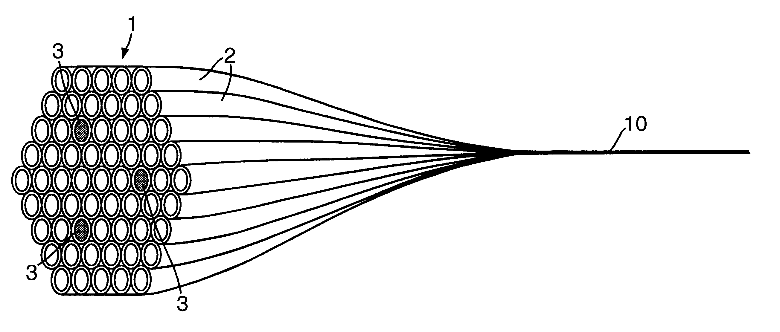
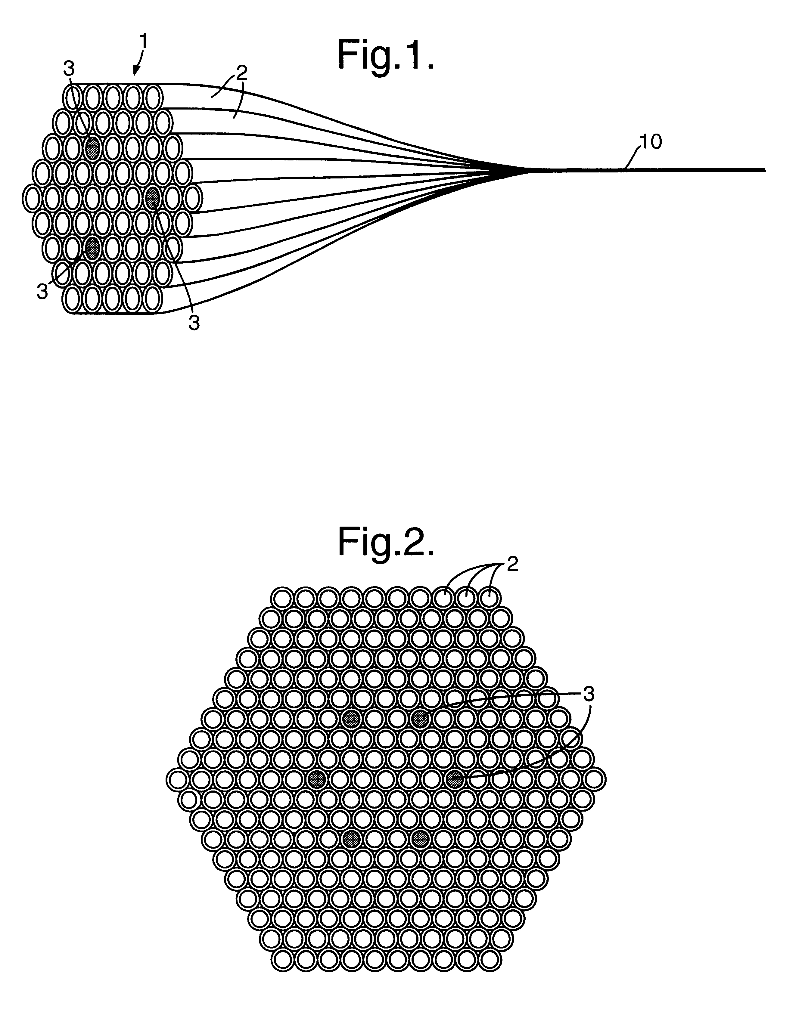
This provides an advantage over known multicore fibre in that, in the preform, the core regions may be automatically positioned in the precise geometry required without the need for accurate machining and assembly of single-core preforms. In addition, each core region may be single mode over a wide wavelength range.

Problems solved by technology

However, at present there are relatively few applications for multicore optical fibres.
This is because it is very difficult to make multicore fibres with the required uniformity and geometrical accuracy.
This process, starting from a number of single core preforms, is a time-consuming and costly process.
Furthermore, the addition of each extra core adds further complexity to the multicore preform.
Higher multiplicity core fibres are therefore increasingly difficult to fabricate.

Method used


Image

  • Multicore optical fibre
  • Multicore optical fibre

Examples


Embodiment Construction

Single-core photonic crystal fibre is made by a stack and draw process as described by J. C. Knight et al., "All silica single-mode optical fiber with photonic crystal cladding", Optics Letters 21 (1996) 1547-1549. The fibre comprises a cladding of an array of air holes that run along the length of the fibre. The holes are arranged in a hexagonal honeycomb pattern across the cross-section, with a spacing of the order of microns. Such a repeating structure with a period of the order of an optical wavelength is called a photonic crystal. However, the central hole is absent, leaving a solid silica "defect" in the crystal structure that acts as the core of the fibre. Light is guided in this core by total internal reflection from the cladding, which effectively has a lower refractive index. The effective index of the photonic crystal cladding has unusual properties that can enable the fibre to be single-mode under all circumstances, unlike conventional step-index fibres. This property is...


PUM

PropertyMeasurementUnit
refractive indexaaaaaaaaaa
internal diameteraaaaaaaaaa

Abstract

An optical fiber for transmitting radiation comprising two or more core regions, two or more core regions, each core region comprising a substantially transparent core material and having a core refractive index, a core length, and a core diameter, wherein said core regions are arranged within a cladding region, said cladding region comprising a length of first substantially transparent cladding material, having a first refractive index, wherein said first substantially transparent cladding material has an array of lengths of a second cladding material embedded along its length, wherein the second cladding material has a second refractive index which is less than said first refractive index, such that radiation input to said fiber propagates along at least one of said core regions. The cladding region and the core regions may be arranged such that radiation input to said optical fiber propagates along one or more said lengths of said core regions in a single mode of propagation. The optical fiber may be used as a bend sensor, a spectral filter or a directional coupler. The invention also relates to a method of manufacturing a multicore optical fiber.

Description

1. Field of the InventionThe invention relates to an optical fibre having at least two cores for propagating radiation. The invention also relates to a method of making such a fibre.2. Discussion of Prior ArtOptical fibres with two cores have been reported and applied to various problems in optical sensing and telecommunications. The potential of multicore fibres with more than two single-mode cores has also been recognized [S. Prasad: "Focusing light into a multiple-core fiber II application to ground-based interferometry", Optics Communications 115 (1995) 368-378]. For example, bend sensing in the plane has been demonstrated using a four-core fibre, using a technique that can readily be extended to the monitoring of bending in three dimensions [M. J. Gander et al., "Bend measurements using multicore optical fiber", presented at OFS 12 1997 ].However, at present there are relatively few applications for multicore optical fibres. This is because it is very difficult to make multicor...

Claims


Application Information

Patent Timeline
Patent Type & Authority Patents(United States)
IPC IPC(8): C03B37/012G02B6/34G02B6/02
CPCC03B37/01205G02B6/02042G02B6/02338G02B6/02347C03B2203/14C03B2203/34C03B2203/42G02B6/021G02B6/02385
Inventor GREENAWAY, ALAN H.LLOYD, PETER A.BIRKS, TIMOTHY A.RUSSELL, PHILIP S.KNIGHT, JONATHAN C.
Owner NKT RES & INNOVATION
Learn More