Drip irrigation lines

a technology of drip irrigation and irrigation line, which is applied in the direction of water supply installation, process and machine control, instruments, etc., can solve the problems of difficult design, clogging of emitters by external particles, and large tendency of external solid particles to enter the line, so as to reduce the sensitivity to clogging and save water

Inactive Publication Date: 2001-10-16
COHEN
View PDF12 Cites 142 Cited by
  • Summary
  • Abstract
  • Description
  • Claims
  • Application Information

AI Technical Summary

Benefits of technology

An object of the present invention is to provide a drip irrigation line having a one-way valve, which is independent of the flow-control passageway of the line, to produce reduced sensitivity to clogging by the entry of external particles via the water dis

Problems solved by technology

However, such emitters may also be clogged by external particles, e.g., dirt entering the emitters via the water discharge openings.
The problem is particularly acute when a drip irrigation line is emptied since this produces a vacuum within the line which tends to suck external particles into the emitter units via the water discharge openings.
For this reason, special pains are frequently taken in installing a drip irrigation line to exp

Method used


Image

  • Drip irrigation lines
  • Drip irrigation lines
  • Drip irrigation lines

Examples


Embodiment Construction

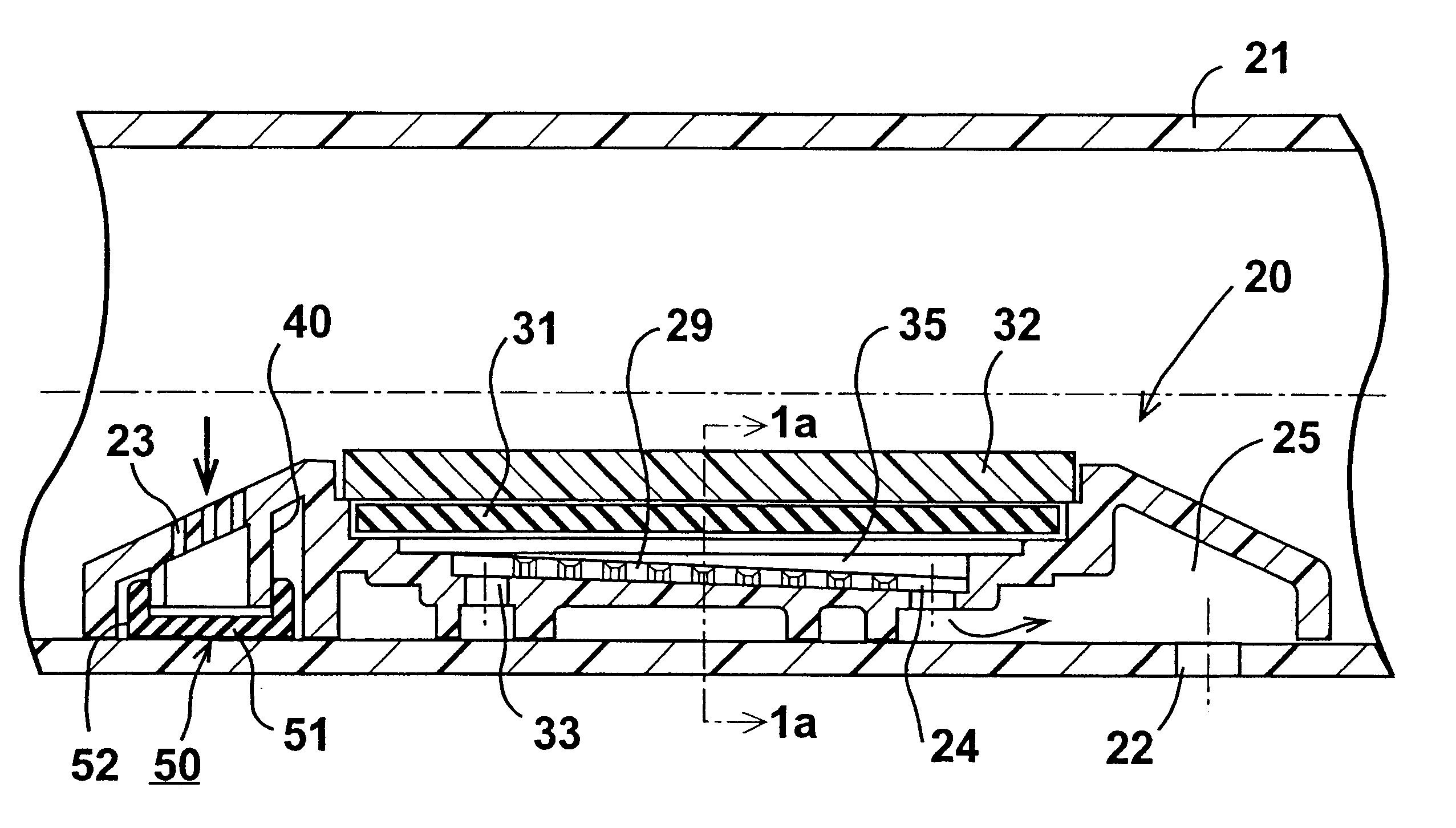
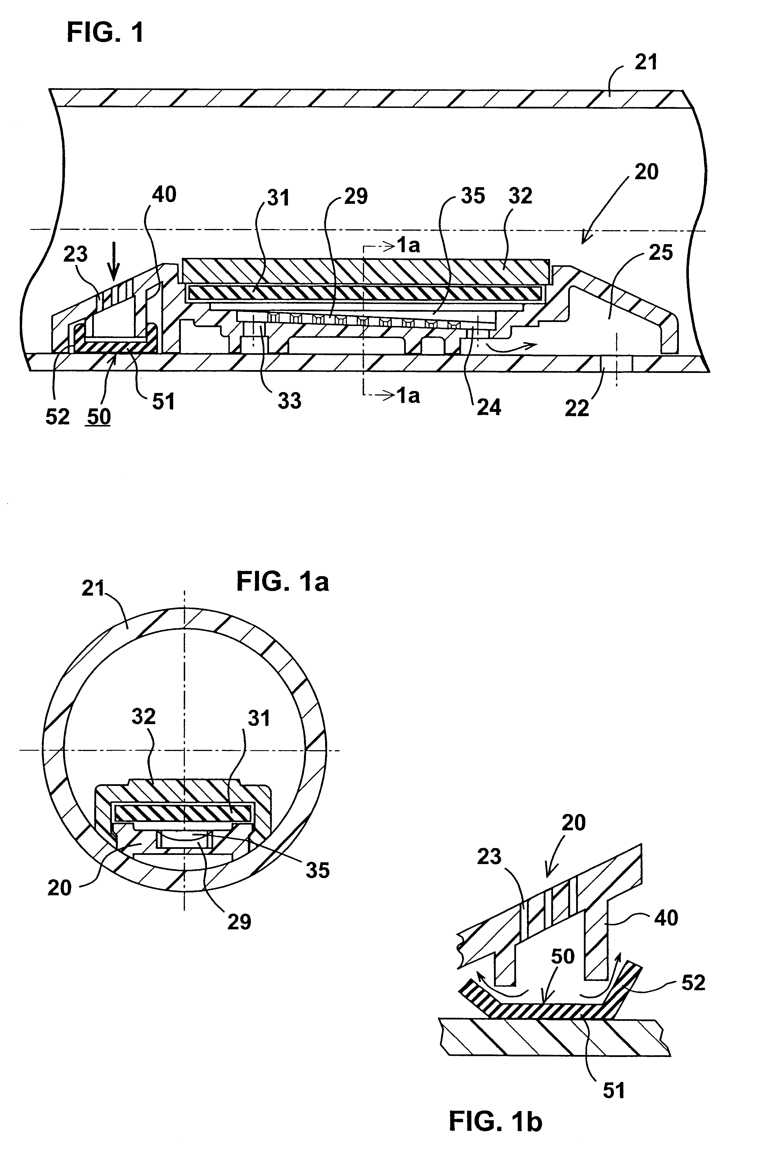
The drip irrigation emitter line illustrated in FIG. 1 is of the type described in my prior U.S. Pat. Nos. 5,400,973, 5,609,303 and 5,634,594, the disclosures of which are hereby incorporated by reference, except that the illustrated emitter unit has been modified in accordance with the present invention.

Thus, the drip irrigation line illustrated in FIG. 1 includes a plurality of emitter units, only one of which is shown at 20, secured as by heat welding, within the water supply tube 21 so as to define a flow control passageway communicating with the interior of the water supply tube, and a water discharge opening 22 in the water supply tube.

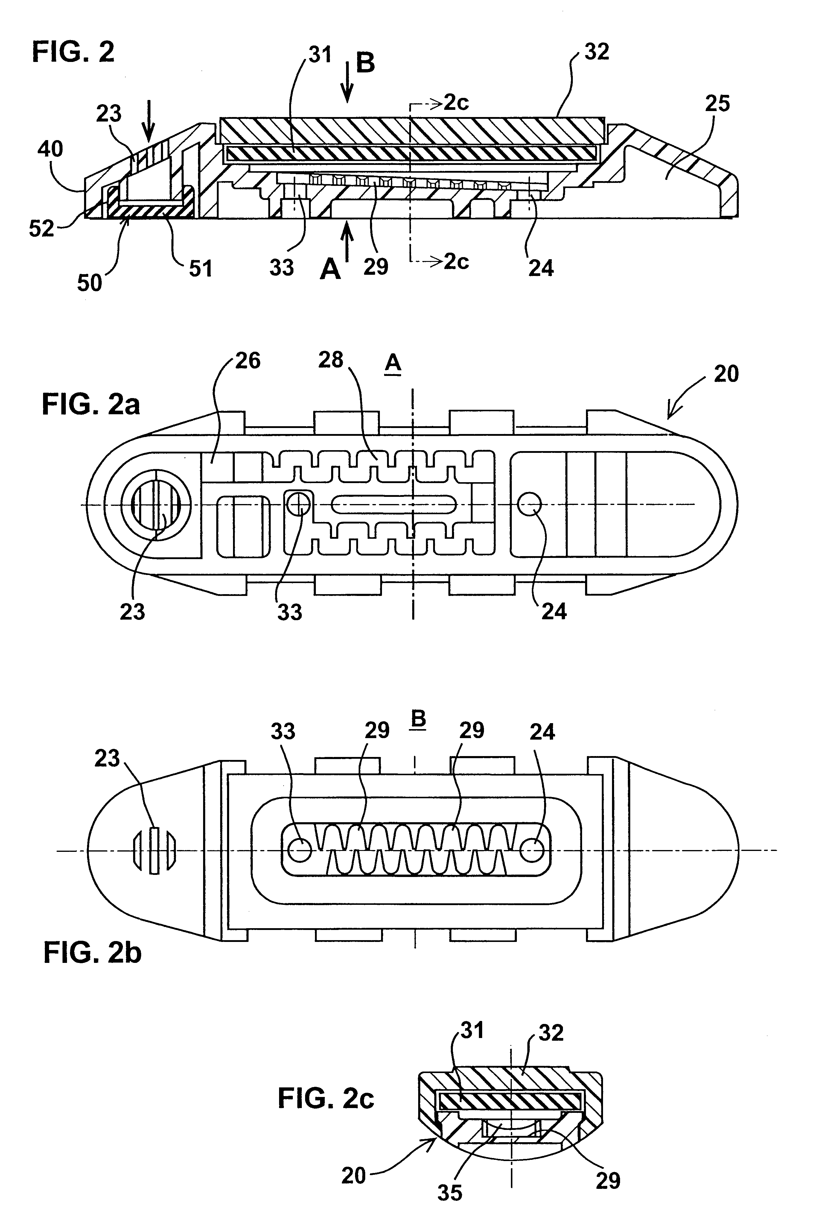
The inlet port to the flow control passageway defined by the emitter unit 20 is in the form of a plurality of narrow slits 23 which filter the water before reaching the flow-control passageway. The outlet port 24 from the flow control passageway leads to a recess 25 aligned with the respective discharge opening 22 in the water supply tube 21.

The...


PUM


Abstract

A drip irrigation line includes a plurality of emitter units secured within a water supply tube such that each emitter unit defines with the tube a flow-control passageway having an inlet port communicating with the interior of the water supply tube and an outlet port communicating with a water discharge opening in the water supply tube. Each emitter unit includes a one-way valve at one of the ports. Such port has an opening circumscribed by a cylindrical boss, and the one-way valve thereat includes a cap having a skirt of elastomeric material normally engaging the outer surface of the cylindrical boss to block reverse water flow into the flow-control passageway, but is deformable under water pressure to permit forward flow from the tube interior into the flow-control passageway.

Description

FIELD AND BACKGROUND OF THE INVENTIONThe present invention relates to drip irrigation lines, and particularly to drip irrigation lines which include a plurality of emitter units secured within a water supply tube for discharging water therefrom at a low rate.Irrigation emitters are commonly constructed with relatively large passageways to reduce the sensitivity of the emitter to clogging by particles in the irrigation water. However, such emitters may also be clogged by external particles, e.g., dirt entering the emitters via the water discharge openings. The problem is particularly acute when a drip irrigation line is emptied since this produces a vacuum within the line which tends to suck external particles into the emitter units via the water discharge openings. For this reason, special pains are frequently taken in installing a drip irrigation line to expose the water discharge openings to the air and not to the soil, but even then, there is still a large tendency of external so...

Claims


Application Information

Patent Timeline
IPC IPC(8): A01G25/02F16K15/14
CPCA01G25/023F16K15/145F16K15/148Y10T137/88054Y10T137/789Y02A40/22A01G25/06
Inventor COHEN
Owner COHEN
Why Eureka
Try Eureka