Impact energy absorbing structure for upper part of body of motor vehicle and energy absorber

a technology of energy absorption structure and upper body, which is applied in the direction of roof, doors, pedestrian/occupant safety arrangements, etc., can solve the problems of complex manufacturing and mounting process, and the possibility of the energy absorption characteristic of the energy absorber being affected by such attachment holes

Inactive Publication Date: 2001-10-16
TOYOTA JIDOSHA KK
View PDF19 Cites 41 Cited by
  • Summary
  • Abstract
  • Description
  • Claims
  • Application Information

AI Technical Summary

Benefits of technology

Because the single energy absorber provides protection against an impact load which may act in a plurality of different directions, and because the energy absorber can be made by extrusion molding or the like, the manufacturing process is made easier. In addition because the energy absorber can be attached securely to the structural member or the inner trim member, the mounting process is also made easier.
An impact load from the front acts an the tubular body portion covering the front corner portion and an impact load from the rear acts on the tubular body portion covering the rear corner portion, whereby the tubular body portions are plastically deformed and impact energy is absorbed. In this case, since the respective tubular body portions have polygonal cross-sectional shape, one or a plurality of sides forming a polygon buckle and thereby absorb energy. This guarantees a good energy absorption efficiency.
Because the energy absorber is fixed to the structural member or the inner trim member by the coupling portion, then is no need to provide the tubular body portions of the energy absorber serving to absorb energy with attachment holes. Therefore, there is no possibility of the energy absorption characteristic of the energy absorber being affected by such attachment holes. Also, since the tubular body portions are coupled to each other by the coupling portion, the number of attachment holes to be provided for attachment of the energy absorber can be reduced in comparison with the case where the tubular body portions are not coupled to each other. Further, if the energy absorber is fixed using tapping screws or the like, the number of tapping screws required is small, which leads to a reduction in cost.
The energy absorber, which in formed by extrusion moulding, can be manufactured easily. Also, since the energy absorber is made of a metal, it is possible to obtain an energy absorption characteristic wherein the load rises abruptly. Besides, by merely attaching the energy absorber to the center pillar, the impact energy absorbing structure for the upper part of the body of the motor vehicle can be realized.

Problems solved by technology

This complicates the manufacturing and mounting processes.
Therefore, there is no possibility of the energy absorption characteristic of the energy absorber being affected by such attachment holes.

Method used


Image

  • Impact energy absorbing structure for upper part of body of motor vehicle and energy absorber
  • Impact energy absorbing structure for upper part of body of motor vehicle and energy absorber
  • Impact energy absorbing structure for upper part of body of motor vehicle and energy absorber

Examples


Embodiment Construction

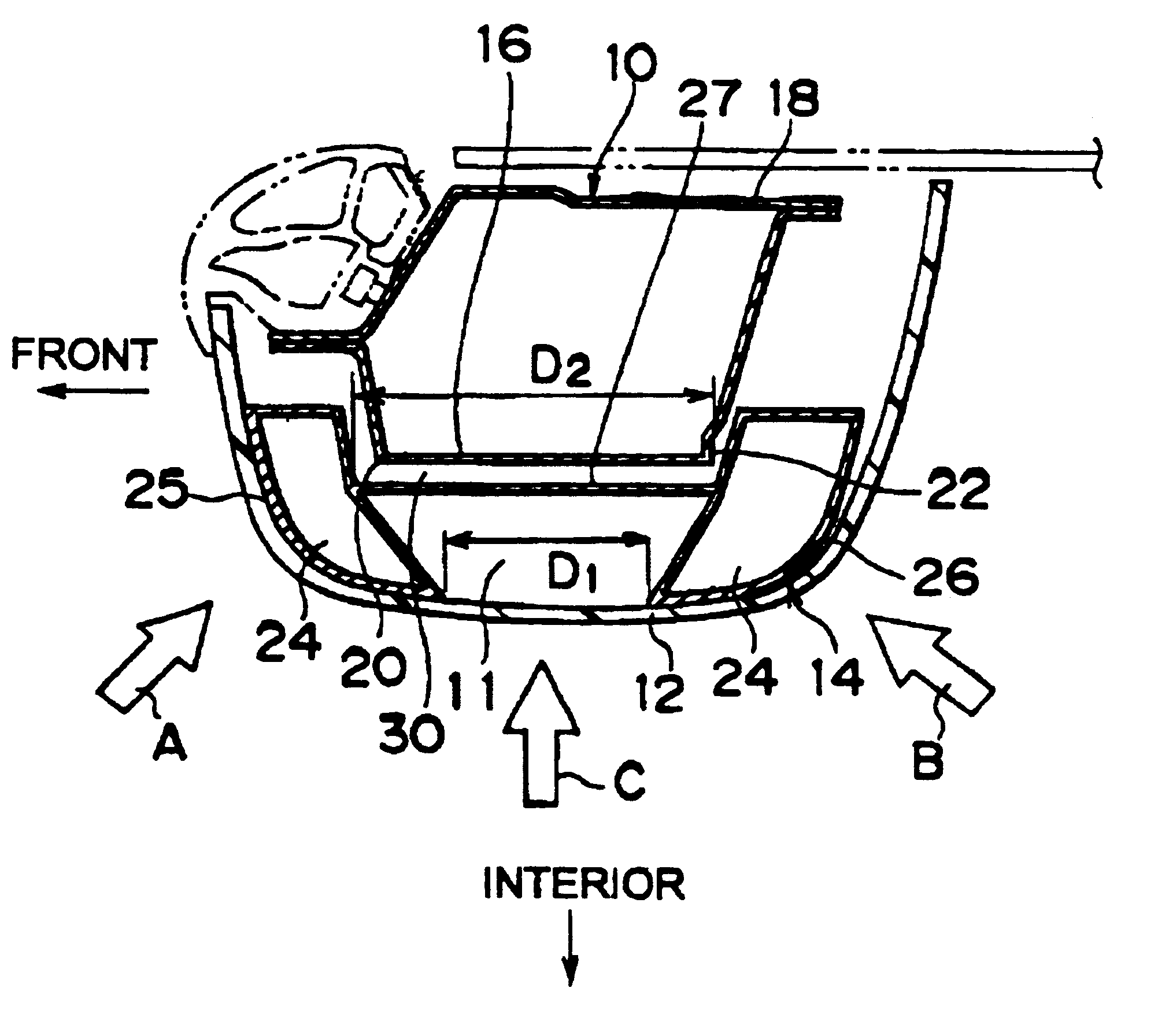
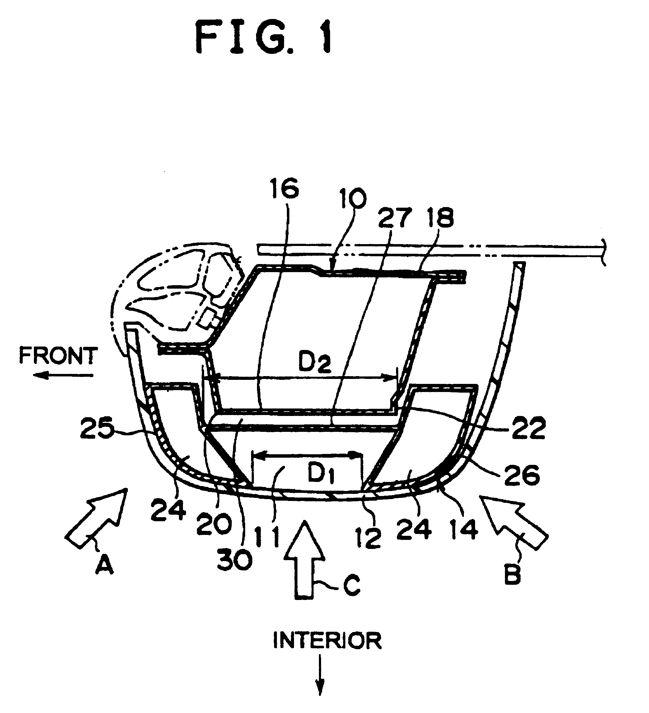
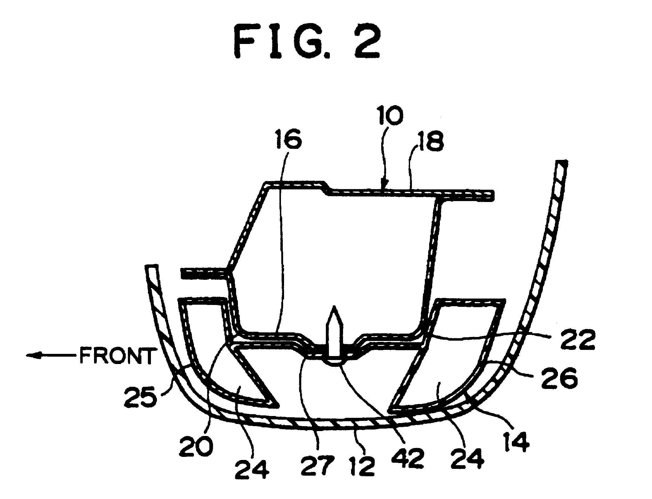
An impact energy absorbing structure according to a first embodiment of the present invention will be described hereinafter with reference to FIGS. 1 through 7.

Referring to FIGS. 1 and 2 which us cross-sectional views of the impact energy absorbing structure and FIG. 3 which is a perspective view of the impact energy absorbing structure, this structure is designed to absorb impact energy in an upper part of a body of a body of a motor vehicle that is equipped with a structural member 10 extending longitudinally and with an interior trim member 12 disposed toward the interior of a cabin and spaced apart from the structural member 10. The impact energy absorbing structure is equipped with an energy absorber 14.

The structural member 10 is a center pillar which, is, made by laying a flange of an outer panel 18 on a flange of an inner panel 16 and banding the flanges and which has two corner portions 20, 22 that with spaced apart in the fore-to-aft direction in the cabin The inner trim m...


PUM


Abstract

In an impact energy absorbing structure for an upper part of a body of a motor vehicle having a structural member that extends in a longitudinal direction and an inner trim member that is disposed toward an interior of a cabin and spaced apart from the structural member by a certain distance, an energy absorber is disposed within the distance. The energy absorber has two hollow tubular body portions whose axes extend in the longitudinal direction and a coupling portion for coupling the tubular body portions to each other. The two tubular body portions are formed integrally with the coupling portion, and the energy absorber is fixed to the structural member by the coupling portion.

Description

INCORPORATION BY REFERENCEThe disclosure of Japanese Patent Application No. HEI 10-358852 filed on Dec. 17, 1999 including the specification, drawings and abstract is incorporated herein by reference in its entirety.1. Field of the InventionThe present invention relates to an impact energy absorbing structure for an upper part of a body of a motor vehicle, especially of a passenger car, and to an energy absorber.2. Description of the Related ArtIn an upper part of a body of a motor vehicle that is equipped with a structural member that extends in the longitudinal direction and an inner trim member that is disposed toward the interior of a cabin and spaced apart from the structural member by a certain distance, then is proposed a construction wherein an extruded metal hollow body is disposed within the distance so as to absorb impact energy.This impact energy absorbing structure cam be manufactured easily because the extruded metal hollow body is used as an energy absorber. Also, the...

Claims


Application Information

Patent Timeline
Patent Type & Authority Patents(United States)
IPC IPC(8): B60R22/18B60R22/24B60R21/055B60R21/02B60R21/04B60R13/02B62D25/04
CPCB60R13/0206B60R21/04B60R21/055B60R22/24B60R2021/0435
Inventor SATOU, TOSHIKATSU
Owner TOYOTA JIDOSHA KK
Why Eureka
Try Eureka