

Photoluminescent emergency egress pathway marking system
a technology of emergency egress pathway and photoluminescent, which is applied in the direction of lighting, lighting and heating equipment, instruments, etc., can solve the problems of power supply wiring, battery damage, power supply failure, etc., and achieve the effect of a large charging area
- Summary
- Abstract
- Description
- Claims
- Application Information
AI Technical Summary
Benefits of technology
Problems solved by technology
Method used
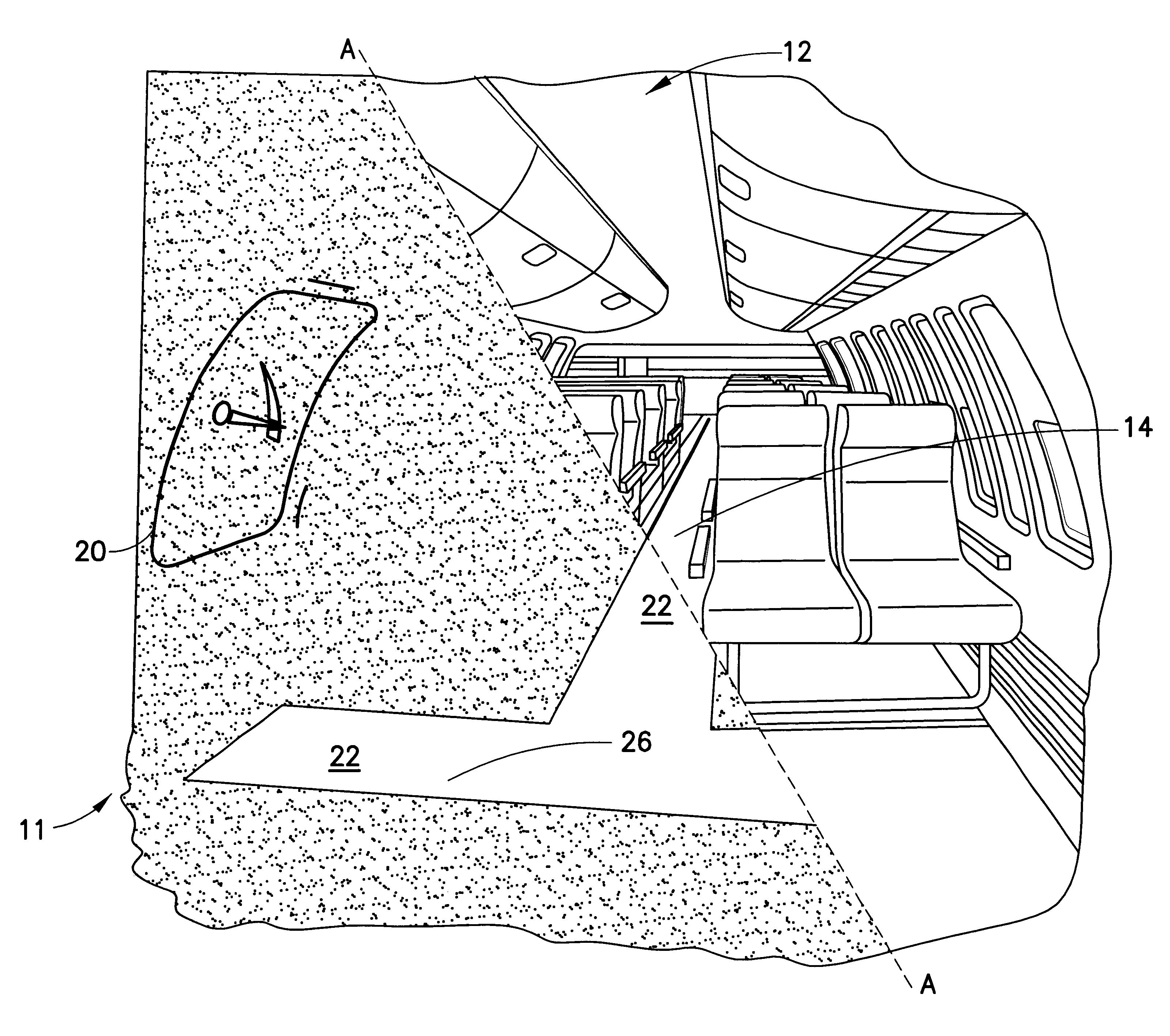
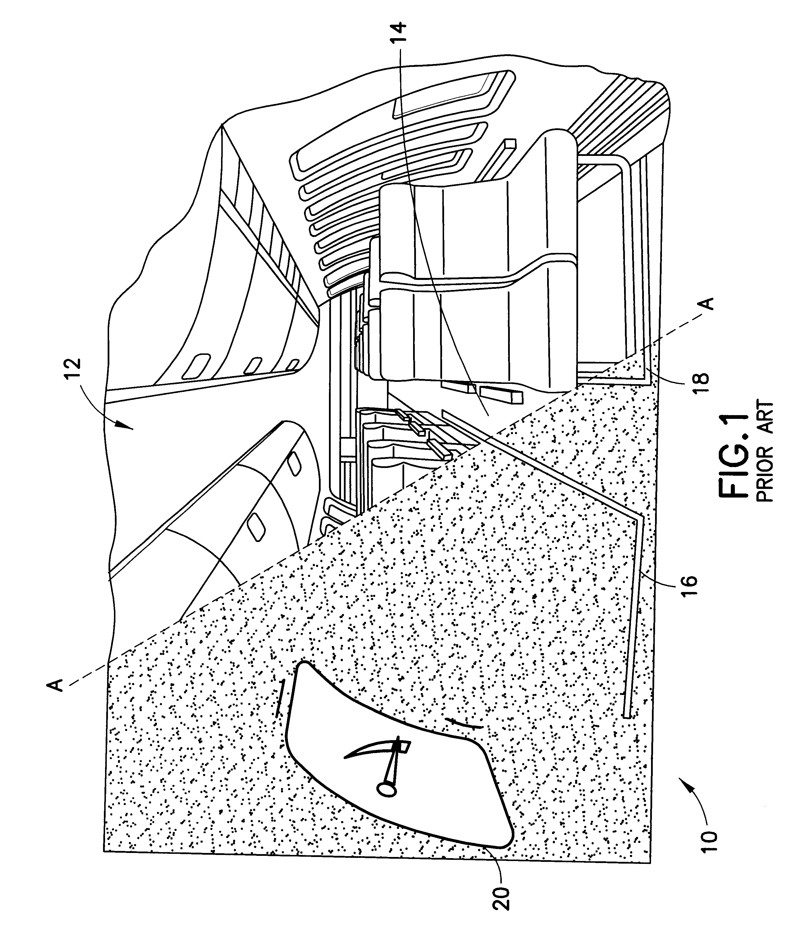
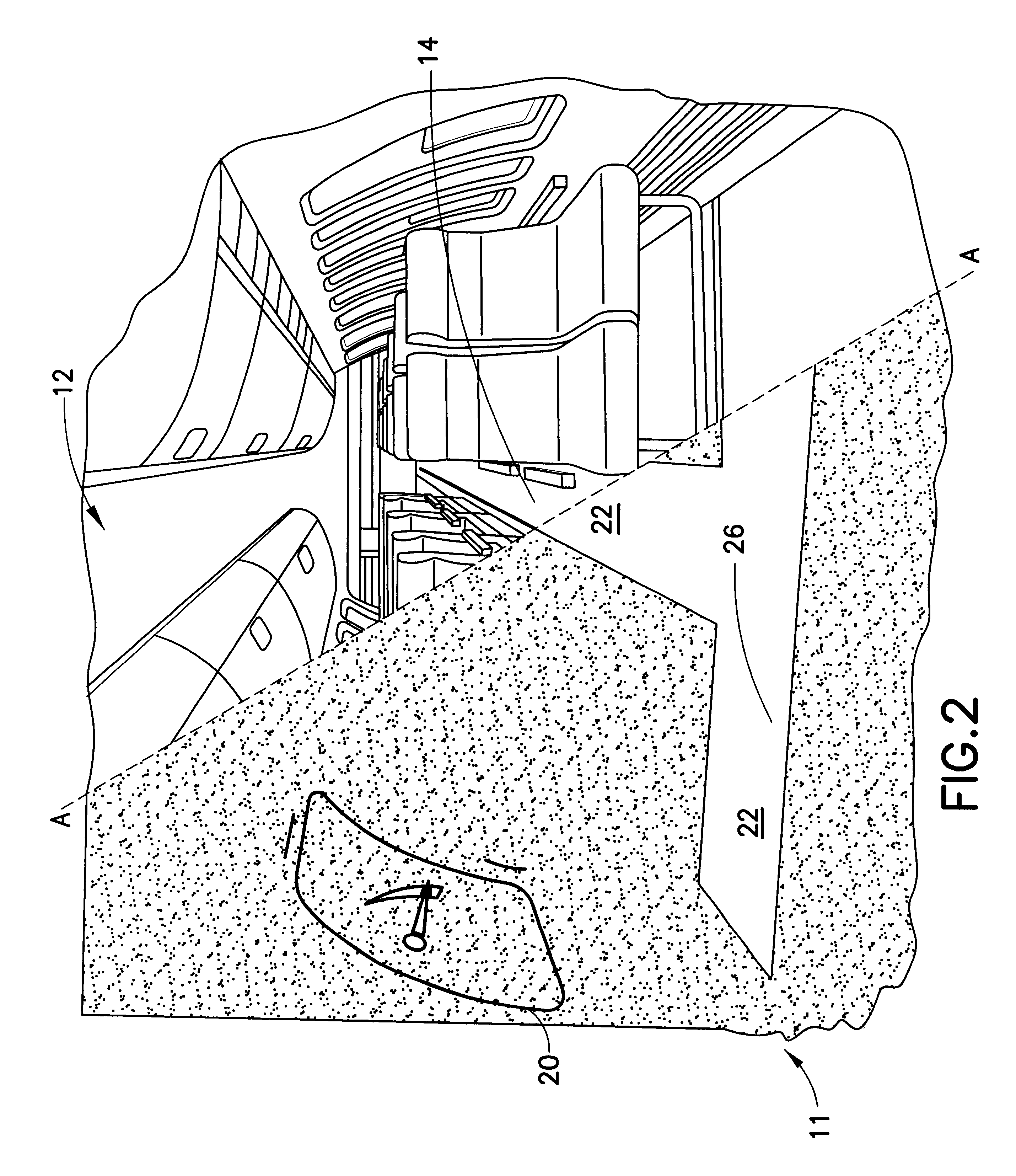
Image

Examples
example
Illumination energy and rate of decay of illumination for a photoluminescent carpet yarn was tested.
A photoluminescent carpet yarn sample was manufactured by Shaw Industries of Dalton, Ga., incorporating photoluminescent fiber woven substantially uniformly throughout the sample. The sample was "dark adapted" (isolated from light) for 16 hours. The sample then was exposed to 40 Lux of luminous energy from a fluorescent light source for 30 minutes, following which the light source was removed and a PR1530 instrument was used to measure the luminance of the sample at 10-minute intervals. A plot of the resultant data is set out in FIG. 5.
FIG. 5 depicts the intensity and decay of luminous energy emanating from the above-described photoluminescent yarn, measured in luminescence (luminance) units of 10.sup.-3 cd / m.sup.2 as a function of time in minutes.
As shown by the FIG. 5 graph, during the period of 0 to 10 minutes, there is a steady diminution of light emission, with the luminance ther...
PUM
| Property | Measurement | Unit |
|---|---|---|
| Length | aaaaa | aaaaa |
| Photoluminescence | aaaaa | aaaaa |
| Phosphorescence quantum yield | aaaaa | aaaaa |
Abstract
Description
Claims
Application Information