Optical fiber communication system incorporating automatic dispersion compensation modules to compensate for temperature induced variations

a technology of optical fiber communication and temperature variation, applied in multiplex communication, transmission monitoring, instruments, etc., can solve the problems of limiting bandwidth and/or transmission distance, subjecting different wavelength components to slightly different propagation time delays, and increasing the effect of temperature variation by a factor

Inactive Publication Date: 2001-10-23
FURAKAWA ELECTRIC NORTH AMERICA INC
View PDF4 Cites 42 Cited by
  • Summary
  • Abstract
  • Description
  • Claims
  • Application Information

AI Technical Summary

Benefits of technology

A high speed optical communication system (.gtoreq.10 Gbit/s) is can be compensated for temperature variation by providing it with one or more automatic dispersion compensation modules. Each module has an adjustable dispersion element, a data integrity monitor and a feedback network whereby the monitor adjusts the dispersion element to compensate for temperature variation. In a preferred embodiment the dispersion compensating module com

Problems solved by technology

Variations in temperature change the group velocity dispersion (GVD) of silica fiber, subjecting different wavelength components to slightly different propagation time delays.
Such dispersion can give rise to undesirable distortion of transmitted light pulses which, in turn, can limit bandwidth and/or transmission distances.
Thus in contemplated systems having four times the current bit rate (contemplated 40 Gbit/s system

Method used


Image

  • Optical fiber communication system incorporating automatic dispersion compensation modules to compensate for temperature induced variations
  • Optical fiber communication system incorporating automatic dispersion compensation modules to compensate for temperature induced variations
  • Optical fiber communication system incorporating automatic dispersion compensation modules to compensate for temperature induced variations

Examples


Embodiment Construction

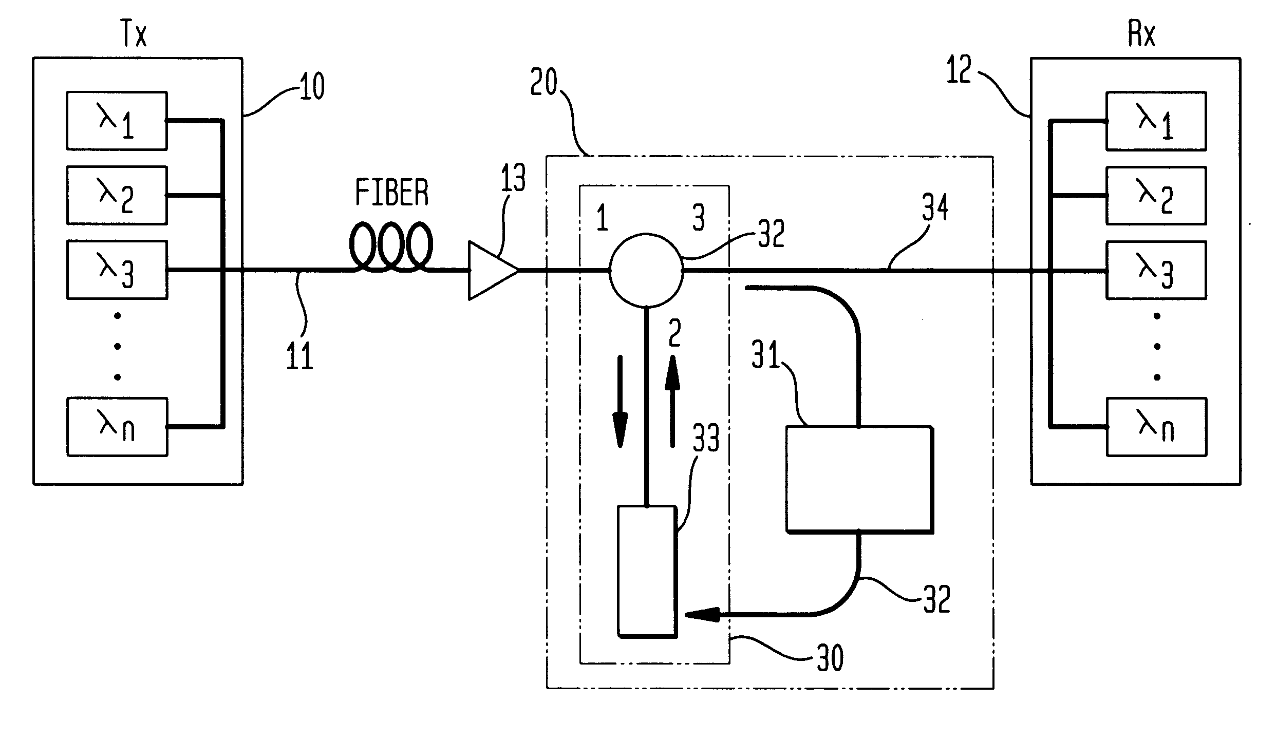
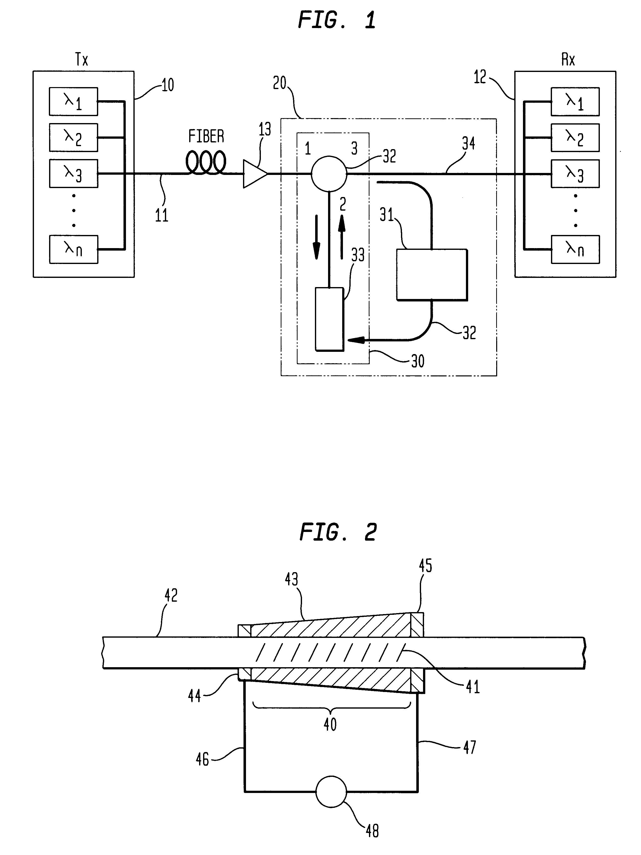
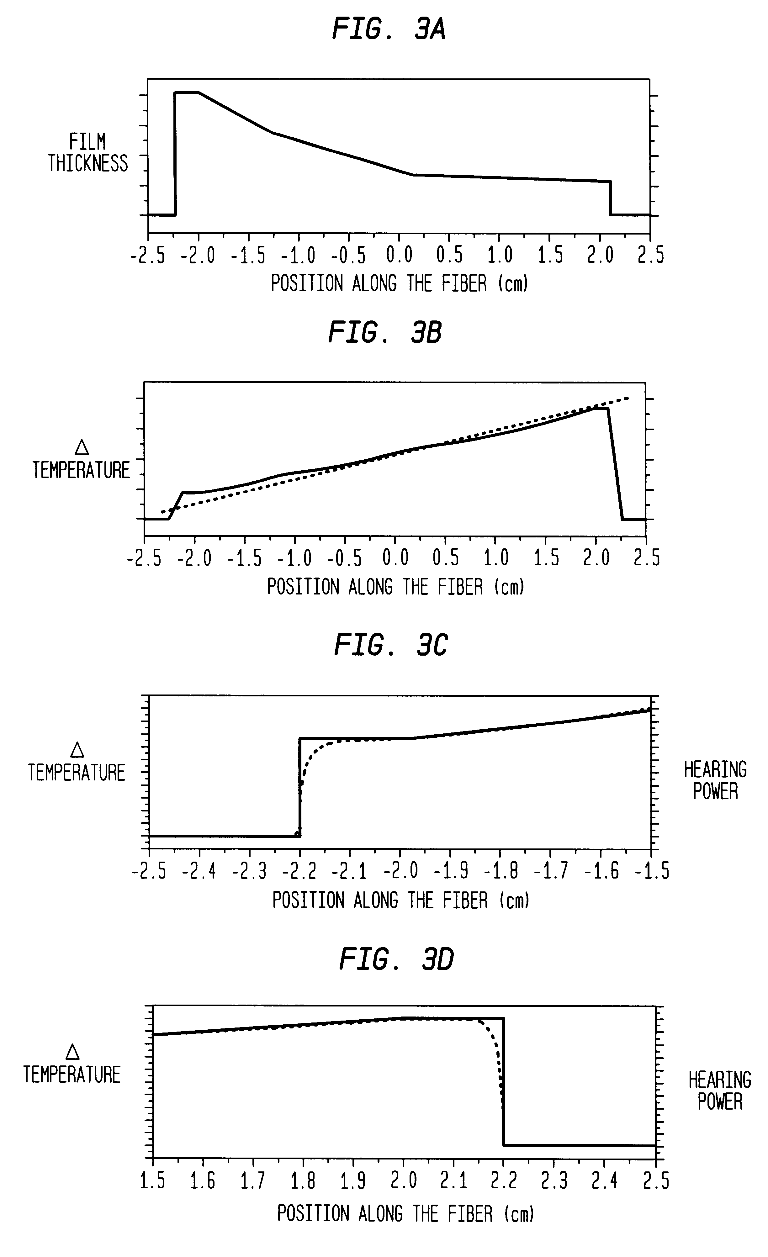
We present detailed results on a fiber grating device that provides constant dispersion over its bandwidth and that can be dynamically adjusted by varying an applied voltage. This device relies on a linear temperature gradient induced along the length of the grating by resistive heating in a metal coating whose thickness varies inversely with position along the length of the fiber. The chirp rate, and thus the dispersion, is controlled by varying the applied current. Numerical modeling and experimental evidence confirms that, to a very good approximation, the temperature varies linearly along the length of the grating and the resulting chirp is linear. We demonstrate experimentally continuous tuning of the dispersion from 300 ps / nm to 1350 ps / nm, with less than 1 W of electrical power. Measurements of the grating dispersion characteristics reveal a group delay ripple with an average deviation from linearity of approximately 10 ps, indicating that the device would be well suited to o...


PUM


Abstract

A high speed optical communication system (>=10 Gbit/s) is compensated for temperature variation by providing it with one or more automatic dispersion compensation modules. Each module has an adjustable dispersion element, a data integrity monitor and a feedback network whereby the monitor adjusts the dispersion element to compensate for temperature variation. In a preferred embodiment the dispersion compensating modules comprise chirped fiber Bragg gratings in which the chirp is induced in the grating by passing a current along distributed thin film heaters deposited along the length of the fiber. The magnitude of the applied current determines the dispersion of the grating. A data integrity monitor is configured to sense the integrity of transmitted data and to provide electrical feedback for controlling the current applied to the grating.

Description

The present invention relates to an optical fiber communication system incorporating automatic dispersion compensation modules in order to compensate for temperature induced variations in the dispersion of the fiber.Optical fiber communication systems are beginning to achieve their great potential for the rapid transmission of vast amounts of information. In essence, optical fiber system comprises a source of information-carrying optical signals, an optical fiber transmission line for carrying the optical signals and a receiver for detecting the optical signals and demodulating the information they carry. Optical amplifiers are typically located along the line at regular intervals, and add / drop nodes are disposed at suitable locations for adding and dropping signal channels.Variations in the temperature of an optical fiber can affect its transmission properties. Optical communication systems are usually based on high purity sitica optical fiber as the transmission medium. Variations...

Claims


Application Information

Patent Timeline
IPC IPC(8): H04B10/18H04B10/02G02B6/00G02B6/02H04L1/00
CPCH04B10/2519H04B2210/252
Inventor EGGLETON, BENJAMIN JOHNROGERS, JOHN A.STRASSER, THOMAS ANDREWWALKER, KENNETH LEE
Owner FURAKAWA ELECTRIC NORTH AMERICA INC
Why Eureka
Try Eureka