Universal power generator utilizing wind flow of liquid for the manufacturing of water from humid air

a technology of wind flow and power generator, which is applied in the direction of defrosting, greenhouse gas reduction, domestic cooling apparatus, etc., can solve the problems of not universal, low efficiency of devices, and not using the energy of wind or waves

Inactive Publication Date: 2001-10-30
EYLMAN LEONID
View PDF7 Cites 25 Cited by
  • Summary
  • Abstract
  • Description
  • Claims
  • Application Information

AI Technical Summary

Benefits of technology

It is, therefore, an object of the universal power generator to eliminate the above disadvantages and to provide the universal power generator which can be d

Problems solved by technology

Since the blades in these prior inventions always rotate an acute angle with the direction of wind or flow devices have very low efficiency.
Also they are not universal and can not use the energy of wind or waves.
The pendulum mechanism, however, is not useful for generating electric energy because of the slow speeds of movement of the inductor (i.e. pendulum) with respect to the stator (in which the electric current is to be induced).
When the inductor moves with a law speed, the generator can not operate with enough efficiency.
When larger wind forces are used, then Smith's pendulum becomes unstable; and the pendulum system loses its main property, which is the stability of operation.
This, in turn, results in the loss of the potential for making the system universal, which is central to the universal power generator described in this patent specification.
The R. Smith device can not work in the sail-vane mode and can not be synchronized with a paddle system any kind such as are described in this patent specification.
Such device can neither generate high power, utilize strong wind

Method used


Image

  • Universal power generator utilizing wind flow of liquid for the manufacturing of water from humid air
  • Universal power generator utilizing wind flow of liquid for the manufacturing of water from humid air
  • Universal power generator utilizing wind flow of liquid for the manufacturing of water from humid air

Examples


Embodiment Construction

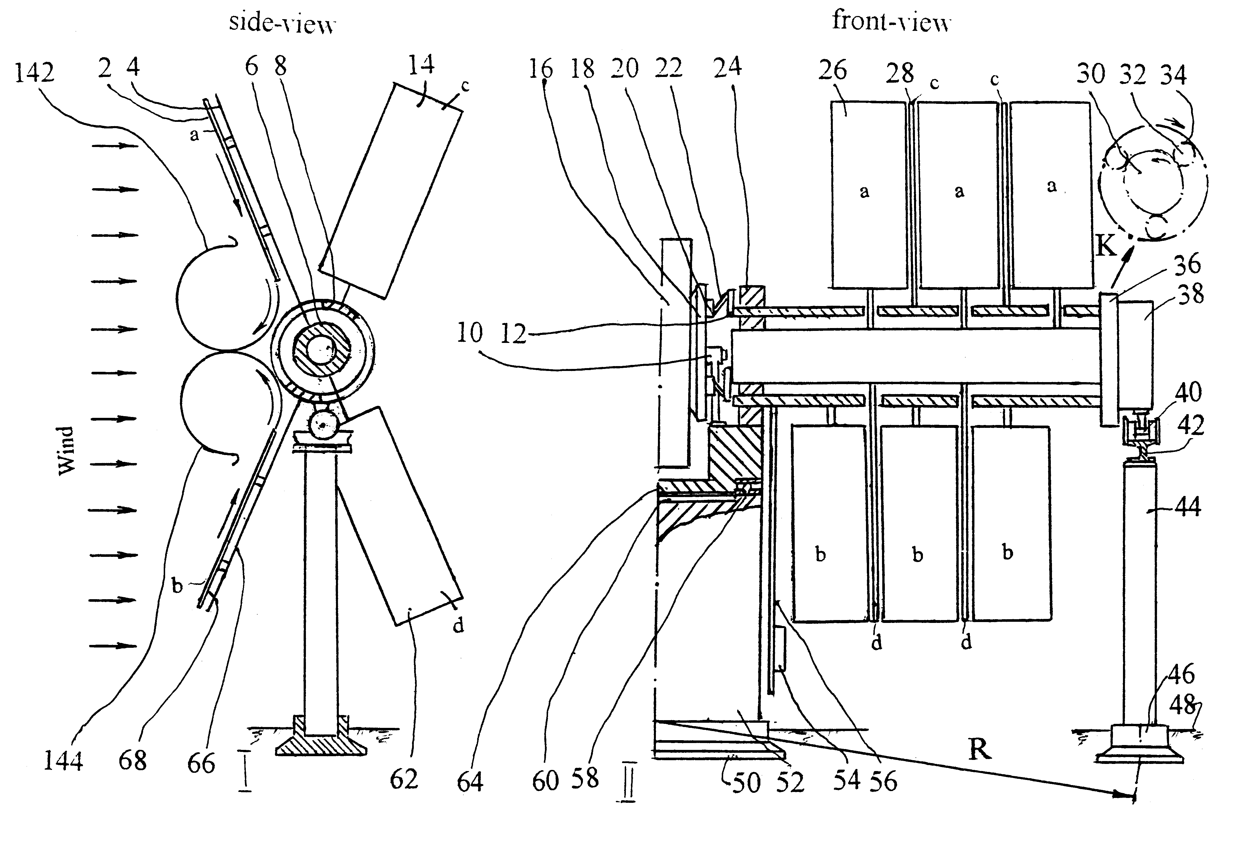
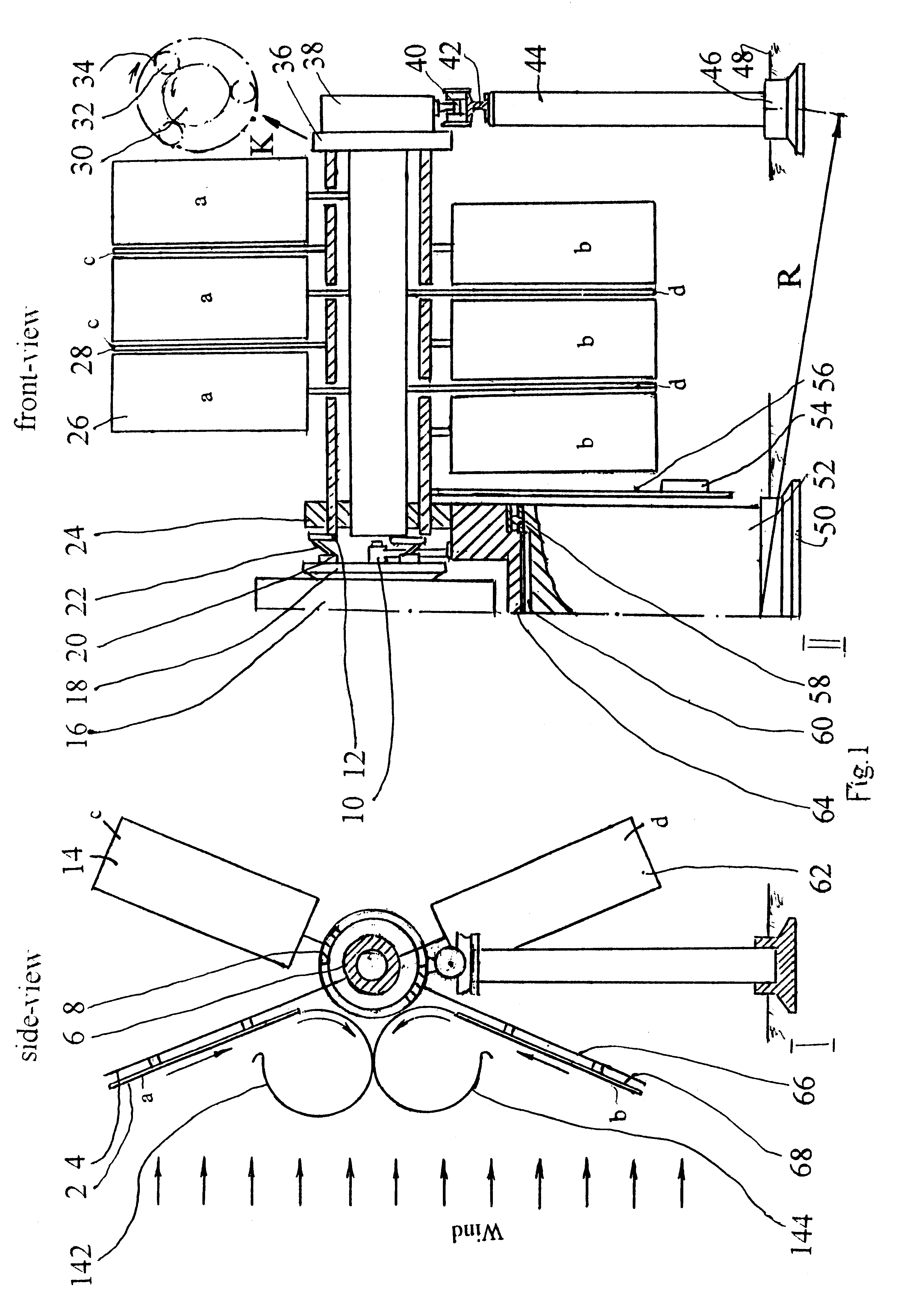
The universal power generator utilizes a combined energy of wind, flow of liquid (for example, ocean stream, sea waves) and solar energy (from the solar cells, which can be fixed on the upper blades "a" and "c". See FIG. 1) is shown in FIG. 1 schematically.

The universal power generator is comprised of a vertical central supporting column 52, which has a bearing 58 and a bracket 10; several columns 44, which are disposed peripherally and which support a railway 42 with the radius R. Two horizontal pivoted tubes, which use as the axle 6 and the axle 8, accordingly. They lie on the bearings 24, 38, which is located between the central column 52 and railway trolley 40 symmetrically.

The sail blades 2 ("a") and 62 ("d") are attached to the tube axle 6. The tube axle 6 and above blades dispose in the frame 4. The sail blades 14 ("c") and 68 ("b") are attached to the tube axle 8. The tube axle 8 and above blades dispose in the frame 66.

The tube axles 6, 8, with corresponding the frames 4, 6...


PUM


Abstract

The universal power generator utilizing the energy of wind, water stream, or a sea waves for manufacturing clean water from humid air is shown in FIG. 1 by the side 1 and front 11 views.The above generator contains the following units: swing system which are comprised of the pendulum system (54,56) sail blade systems (2,4,66,68). The sail system is formed of a plurality of blades (a, b, c, d) installed on two frames (4,66), which swing on two horizontal axles (6,8) which are disposed according to the wind direction or the flow of water movement by weather cock system. The tips of the lower blades can be used as paddles.If the upper blades (a) of the frame (4) and the lower blades (b) of the frame (66) receive any stream of energy then the other blades (c) of the frame (66) and lower blades (d) of the frame (4) move in manner like a weather cock at the same time. At the end of each swing, the blades change their action.The design of sails blades allows for a simple regular means of cooling humid air in the special air chambers. The above generator produces electro energy for a cooling from natural, clean and renewable sources of energy, therefore water is extracted from humid air at a very low cost. A set of membranes separates a tiny bit of water from humid air in the special water headers.

Description

The present invention relates to the field of power engineering, particularly to the universal power generator utilizing wind or flow of water energy for manufacturing water from humid air.DESCRIPTION OF PRIOR ARTEfforts to reduce dependence upon fossil fuels, as well as stringent environmental requirements with regard to air pollution have lead to an increasing demand for efficient and reliable generators of electric power which can operate from wind, energy of waves, and the flow of liquids.The power generators driven by wind or flow of liquid are known in the art. Such wind turbine generators are described in U.S. Pat. No. 4,545,728 to Marvin Cheney, Jr., November 1985 and etc. This list can be extended to a substantial number of patent and literature sources. What is common amongst all existing power generators driven by wind and flow of liquid is that all of them have an turbine or impeller with different types of blades which are attached to a common axle or shaft. Since the b...

Claims


Application Information

Patent Timeline
IPC IPC(8): E03B3/00E03B3/28F03D9/00
CPCE03B3/28F03D9/00F05B2210/16F05B2220/61F05B2220/62Y02E10/725Y02E70/10Y02A20/141Y02E60/16F03D9/25F03D15/10F03D9/20F03D9/12Y02A20/00Y02E10/72Y02E60/36Y02E70/30
Inventor EYLMAN, LEONID
Owner EYLMAN LEONID
Why Eureka
Try Eureka