
Hologram

a hologram and hologram technology, applied in the field of holograms, can solve the problems of poor solvent resistance and chemical resistance, poor quality reliability in high temperature environments, and change in hologram properties,

Inactive Publication Date: 2001-11-13
DENSO CORP
View PDF9 Cites 83 Cited by
  • Summary
  • Abstract
  • Description
  • Claims
  • Application Information

AI Technical Summary

Problems solved by technology

They also have a problem of susceptibility to moisture absorption which leads to changes in the hologram properties.
Also, while hologram elements made of photopolymers are moisture-resistant, they also have problems of poor solvent resistance and chemical resistance.
For this reason, they have had poor quality reliability in high temperature environments and high temperature, high moisture environments.
However, the following problems have been associated with the conventional means for protecting hologram elements.
First, with the above-mentioned first means for using hologram elements made of gelatin dichromate, the use of glass plates has been an obstacle to weight reduction of the hologram elements, while their possible uses have been limited because of the reduced degree of design freedom, since the shape must be flat.
With the second means, production under ultralow humidity conditions has resulted in poor manageability.
The first means for using hologram elements made of photopolymers is limited to cases where the hologram element is a polyvinyl carbazole system, because when other photopolymers are used certain problems occur such as changes in the properties of the hologram caused by solvents or chemicals, discoloration of the hologram element, and inferior durability.
Also, with the second means, there has been a problem in that air bubbles become included in the adhesive during adhesion of the hologram element, thus altering the optical properties of the hologram element.
However, although this allows absorption of relatively small air bubbles, the larger air bubbles which are produced during attachment cannot be absorbed.
In addition, after application of the adhesive to the hologram element and attachment to the plate, the adhesive often bleeds out from between them.
Also, when the positions of the hologram element and the plate become shifted and they are then attached with the adhesive, the hologram element and plate become fixed with the adhesive, making it impossible to reposition them afterwards.

Method used


Image

  • Hologram
  • Hologram
  • Hologram

Examples


example 1

A hologram according to an embodiment of the invention will now be explained with reference to FIGS. 1 to 8.

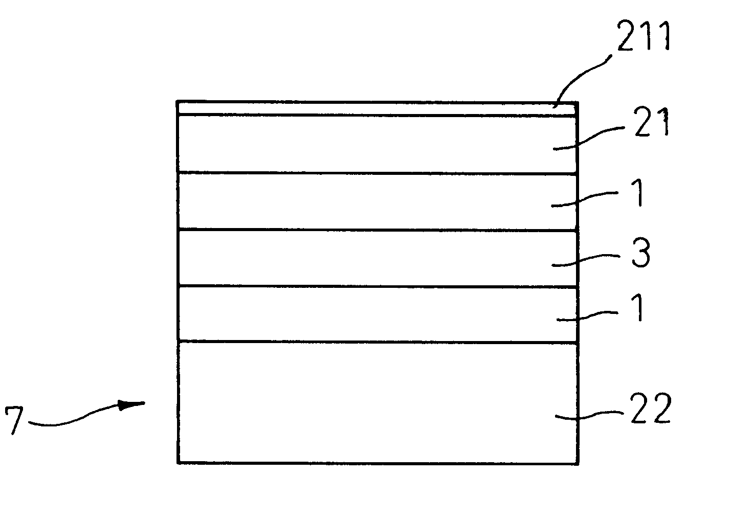
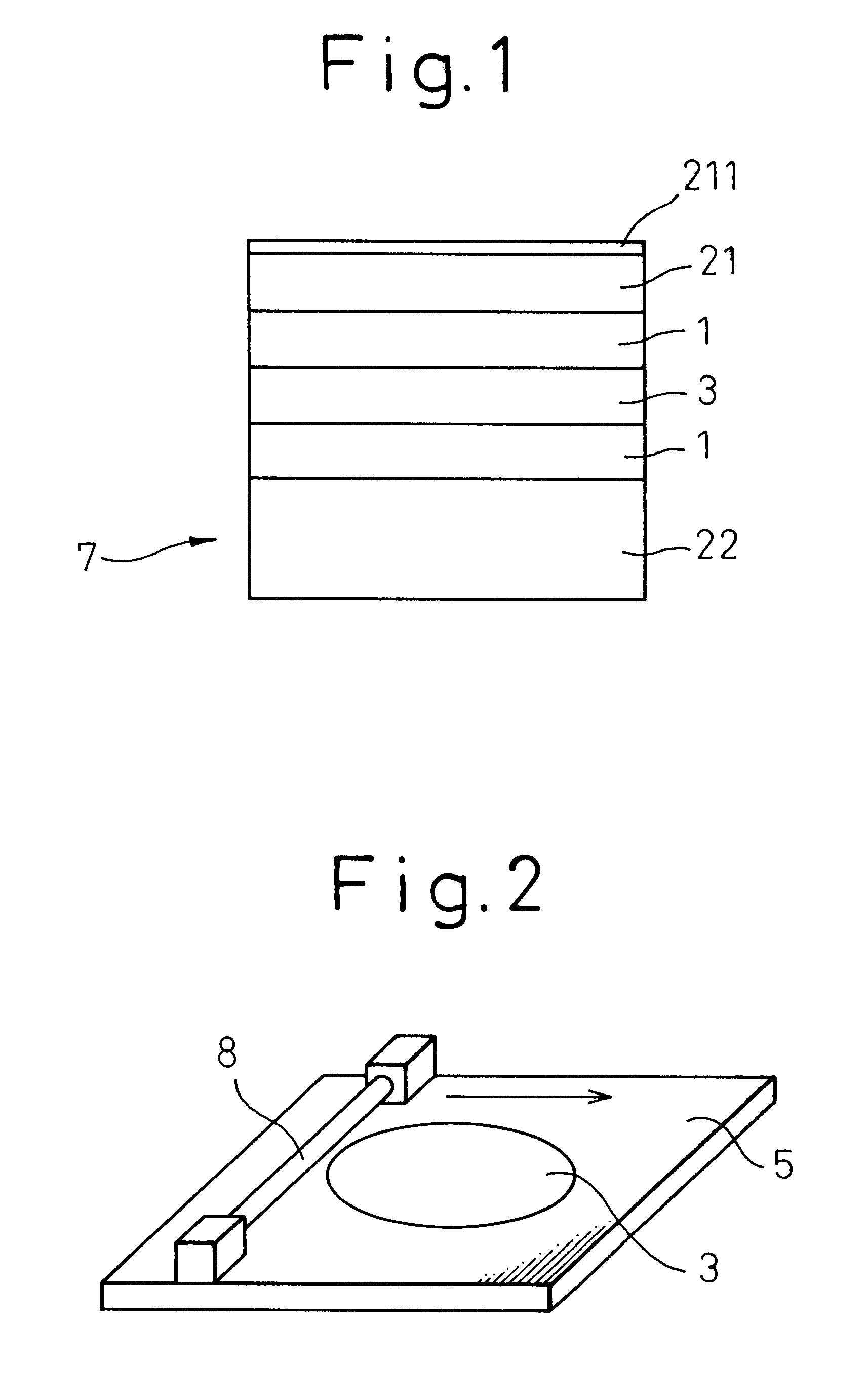
The hologram 7 of this embodiment, as shown in FIG. 1, comprises a hologram element 3 containing a photopolymer, a cover film 21 covering the top side of the hologram element 3 and a cover plate 22 covering the bottom side of the hologram element 3. The hologram element 3 and cover film 21 and the hologram element 3 and cover plate 22 are bonded together with an adhesive 1 consisting of an acrylic resin of molecular weight of 1,000,000.

The method of producing the hologram will now be explained.

First, as shown in FIG. 2, an applicator 8 is used to coat a glass substrate 5 with a photopolymer composition to a dry film thickness of 20-40 .mu.m to form the hologram 3. Other methods include spin coating, dipping and bar coating methods.

Next, heat treatment is carried out for about 30 minutes at a temperature of around 100.degree. C. volatilize and remove the solvent in the hologram...

example 2

This example, as shown in FIG. 9, had a structure wherein one side of the hologram element 3 was coated with a PET film 52 made of polyethylene terephthalate for recording the interference bands on the hologram element, while the other side was attached to a glass substrate 5. The hologram element 3 used was a photopolymer composition of the same material as in Example 1.

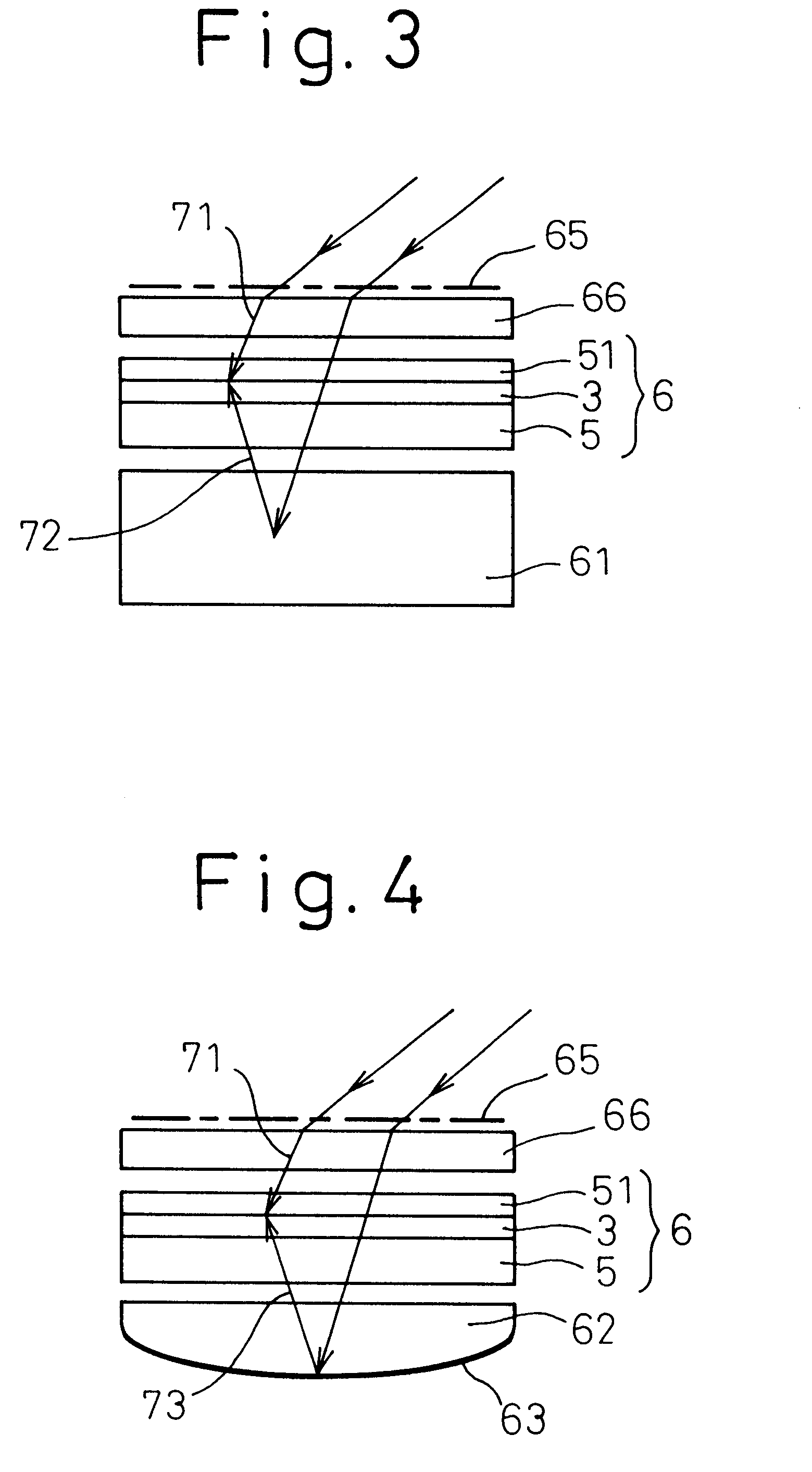
Specifically, the hologram element 3 used was one with a film structure coated on both sides with a PET film. For recording of the interference band, the PET film on one side of the hologram element 3 was released, while the other side was attached to the glass substrate 5 by the tackiness (adhesion) of the hologram element 3, to prepare a photographic plate 6.

A glass plate 66 with an anti-reflection film 65 was positioned on the photographic plate 6.

Next, argon laser light beams 75, 76 were irradiated from the same side of the photographic plate 6 for polymerization of the first monomer of the photopolymer composit...

example 3

In this example, as shown in FIG. 10, the effect of changes in the molecular weight of the adhesive on the durability of holograms at high temperature (high temperature durability) was investigated.

The molecular weight of the adhesive was varied from 500,000 to 1,500,000. The holograms were otherwise produced in the same manner as in Example 1.

Each hologram was placed in a high temperature environment of 100.degree. C. and the change in the reproduction wavelength was measured periodically. The results are shown in FIG. 10.

As seen in this drawing, the holograms having adhesives of molecular weight 1,300,000 and lower exhibited no change in the reproduction wavelength even when allowed to stand for 200 hours and longer, thus demonstrating their excellent durability.


PUM


Abstract

A hologram has a hologram element 3 containing a photopolymer and a cover film 22 and cover plate 21 which cover its surfaces. An adhesive 1 is used for bonding the cover film to the hologram element and the cover plate to the hologram element. The hologram has excellent humidity resistance, chemical resistance, solvent resistance and heat resistance, prevents coloration, can maintain its holographic properties and allows easy repositioning of the hologram element.

Description

1. Field of the InventionThe present invention relates to a hologram and, particularly, it relates to the adhesion between a hologram element and its cover film.2. Description of the Related ArtGelatin dichromate and photopolymers have conventionally been used as photosensitive materials for hologram elements.Hologram elements made of gelatin dichromate have high diffraction efficiency and produce bright reproduction images. They also have a problem of susceptibility to moisture absorption which leads to changes in the hologram properties.Also, while hologram elements made of photopolymers are moisture-resistant, they also have problems of poor solvent resistance and chemical resistance. For this reason, they have had poor quality reliability in high temperature environments and high temperature, high moisture environments.Thus, according to the prior art it has been necessary to protect hologram elements from their environments.In conventional use of hologram elements made of gelat...

Claims


Application Information

Patent Timeline
Patent Type & Authority Patents(United States)
IPC IPC(8): G03H1/02G03H1/00
CPCG03H1/02G03H1/0252G03H2250/10G03H2250/39G03H2260/12
Inventor MIZUTANI, YASUHIROKAWAZOE, NAOYUKIHATTORI, HIDEKAZU
Owner DENSO CORP
Learn More