Measurement device for measuring the mass of a flowing medium

a technology of measuring device and flowing medium, which is applied in the direction of liquid/fluent solid measurement, instruments, machines/engines, etc., can solve the problem that tasks cannot always be reliably fulfilled, and achieve the effect of reducing manufacturing costs, low tolerance, and increasing manufacturing efficiency

Inactive Publication Date: 2001-11-20
ROBERT BOSCH GMBH
View PDF4 Cites 16 Cited by
  • Summary
  • Abstract
  • Description
  • Claims
  • Application Information

AI Technical Summary

Benefits of technology

A principal object of the measurement device according to the invention is to provide the advantage over the prior art that in the manufacturing, a relatively low tolerance must be maintained in the positioning of the sensor element in relation to the recess of the sensor support. As a result, the manufacturing efficiency is increased and the manufacturing costs are reduced. Furthermore, the manufacturing speed can be increased. In another object of the invention the ventilation of the rear of the membrane remote from the flowing medium is reliably assured with a sufficient opening cross section so that a destruction of the sensor element due to pressure peaks is prevented. The glue seam is used simultaneously for tolerance compensation between the sensor element and the sensor support as well as for compensation of different coefficients of thermal expansion.

Problems solved by technology

However, it is disadvantageous in this embodiment that the sensor element must be aligned with high precision in regard to the recess of the sensor support during mounting in order to produce the extremely narrow gap.
But this task cannot always be reliably fulfilled for tolerance reasons and due to manufacturing variations so that not insignificant losses in efficiency occur during manufacture.

Method used


Image

  • Measurement device for measuring the mass of a flowing medium
  • Measurement device for measuring the mass of a flowing medium

Examples


Embodiment Construction

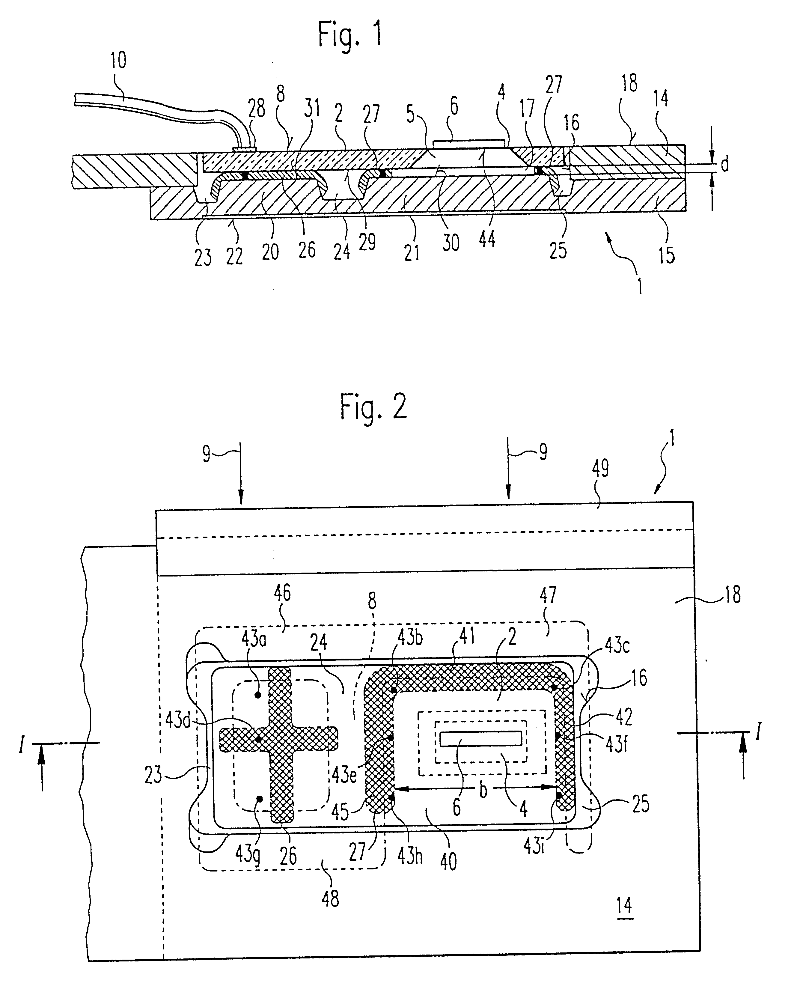
The sensor support 1 depicted in a sectional view in FIG. 1 is provided for a plate-shaped sensor element 2. The sensor support 1 and the sensor element 2 are part of a measurement device not shown in detail, which is for measuring the mass of a flowing medium, in particular the intake air mass of an internal combustion engine.

The sensor support 1 is used to contain and secure the sensor element 2, which has a membrane-shaped sensor region, which is embodied, for example, in the form of a dielectric membrane 4. The sensor element 2 or the membrane 4 can be produced by means of etching a semiconductor body, for example a silicon wafer, in a so-called micromechanical construction, wherein a hollow space 5 is produced underneath the membrane 4. At least one temperature-dependent measurement resistor 6 and for example at least one heating resistor that is not shown, which are for example likewise produced by means of etching, are provided on the membrane 4 in order to measure the mass o...


PUM


Abstract

A measurement device for measuring the mass of a medium flowing along a flow direction, in particular the intake air mass of an internal combustion engine, has a plate-shaped sensor element, which is inserted into a recess of a sensor support. The sensor element includes a membrane that supports a measuring element, which membrane encloses a hollow space embodied in the sensor element on the side remote from the sensor support. The sensor element is secured in the recess by means of a glue between the sensor support and a bottom face of the sensor element oriented toward the sensor support. According to the invention, the glue constitutes a glue seam that extends around the hollow space of the sensor element between the sensor support and the bottom face of the sensor element and is only open on the side remote from the flow direction by means of at least one recess in order to ventilate the hollow space.

Description

The invention is directed to improvements in a measurement device for measuring the mass of a flowing medium.A measurement device has already been disclosed by German Patent Publication 195 24 634 A1, which includes a plate-shaped sensor element with a dielectric membrane that is inserted into a recess of a sensor support. The sensor element is made of a semiconductor material, e.g. silicon, and is manufactured in a micromechanical construction. The membrane is comprised of a dielectric material, for example silicon nitride or silicon oxide. A measurement resistor and a heating resistor are disposed on the dielectric membrane, which are to a large extent thermally insulated from a silicon frame that encompasses the membrane due to the thin embodiment of the membrane and the low heat conductivity of the dielectric membrane. Between the dielectric membrane and the sensor support, there is a hollow space in the plate-shaped sensor element, which extends from a bottom face adjoining the...

Claims


Application Information

Patent Timeline
Patent Type & Authority Patents(United States)
IPC IPC(8): G01F1/69G01F1/684G01F1/68F02D35/00
CPCG01F1/6845G01F1/69G01F1/684G01F1/82
Inventor RENNINGER, ERHARDHECHT, HANSHUEFTLE, GERHARDKONZELMANN, UWEKALLABIS, MATTHIASSTARK, ANDREASRUDLOFF, MICHAELMARBERG, HENNING
Owner ROBERT BOSCH GMBH
Why Eureka
Try Eureka