Methods and apparatus for improved luminescence assays

a luminescence assay and luminescence technology, applied in the direction of diaphragms, combination devices, immobilised enzymes, etc., can solve the problems of only operating for very short distances, it has not appeared possible to use microparticulate matter in the measurement of luminescence phenomena, etc., to achieve faster assay time, improve sensitivity, and improve sensitivity

Inactive Publication Date: 2001-12-04
BIOVERIS CORP
View PDF72 Cites 81 Cited by
  • Summary
  • Abstract
  • Description
  • Claims
  • Application Information

AI Technical Summary

Benefits of technology

It is a further and related object to provide such assays, reagents and apparatus having improved sensitivity, faster assay time, greater sensitivity, lower detection limits and greater precision than has heretofore been achieved.

Problems solved by technology

Based upon this prior art, it would not have appeared possible to use microparticulate matter in assays wherein a luminescent phenomenon is measured.
However, this tunneling phenomenon can only operate for very short distances.

Method used


Image

  • Methods and apparatus for improved luminescence assays
  • Methods and apparatus for improved luminescence assays
  • Methods and apparatus for improved luminescence assays

Examples


third embodiment

In a third embodiment, the particles may be removed by filtration from the assay composition. In this embodiment the particles need not have a density greater than the balance of the assay composition. The invention, the particles are separated from the solution and concentrated by drawing the solution through a filter, e.g. pumping and collecting the particles on the surface of the filter. This surface of the filter is, for example, coated with a thin metal film which can serve as the working electrode in an ECL detection system.

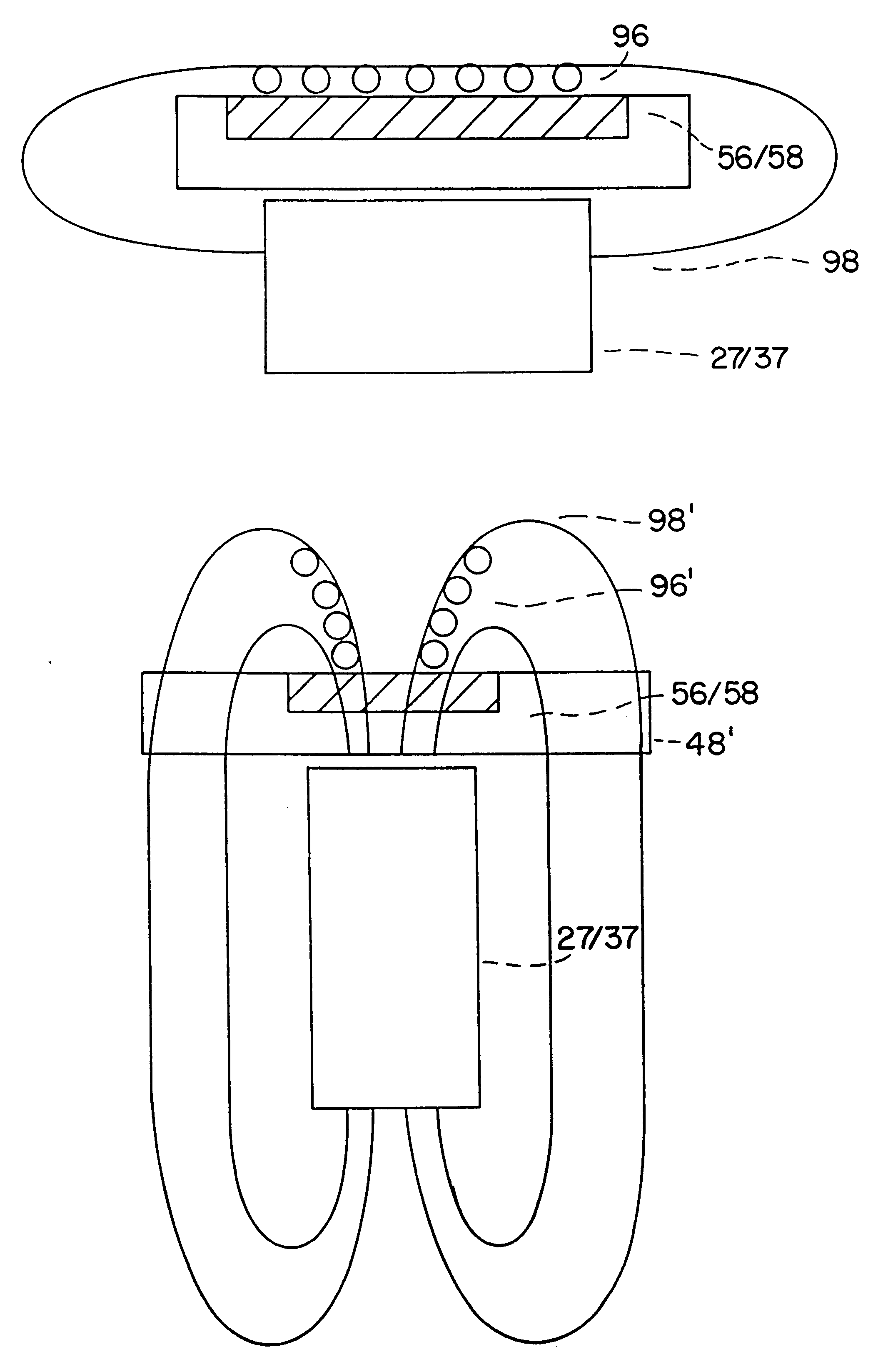
In a preferred embodiment, the suspended particles are magnetically responsive, e.g. they may be paramagnetic or ferromagnetic, and are collected in a measurement zone or, preferably, directly at the surface of an electrode, by imposition of a magnetic field on the particles. The measurement cell is equipped with a magnet. The magnetic field of the magnet applies a force on the particles as they reside in a batch cell or as they flow through a flow cell, ca...

example 1

Apparatus and Method for Collection of Microparticles by Gravity

The measurement is conducted in a cell as shown in FIG. 12. References made to FIG. 12 which depict an apparatus for conducting an assay using the force of gravity. The components of the apparatus include a transparent window identified by reference numeral 11, a gasket identified by reference numeral 12, a block which includes an inlet 13, a working electrode 14, a counterelectrode 15 and an outlet port 16. The plane of the cell block is horizontal, i.e. perpendicular to the direction of the earth's gravitational field. Labeled microparticles (Dynal) in an ECL buffer are drawn to the cell by means of a peristaltic pump. The pump is turned off after the particles reach the cell. The microparticles in the cell chamber fall onto the working electrode surface. The rate of fall of microparticles is determined to be approximately constant at 0.5 mm / min over a distance of 10 mm, as shown in FIG. 13. The number of particles to...

example 2

ECL Apparatus and Method for Deposition of Microparticles.

Magnetic Collection using a Sedimentation Cell.

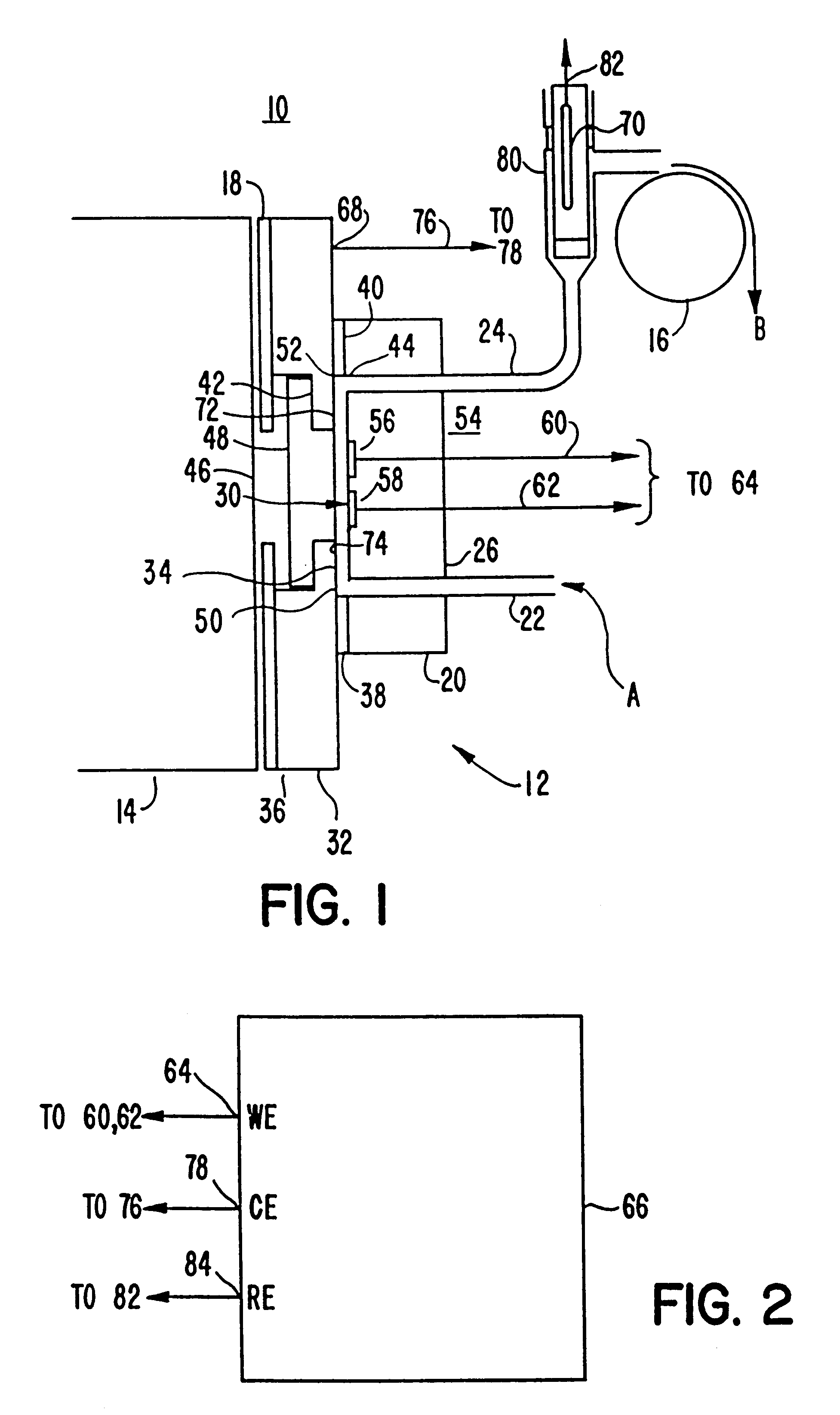
A cell for conduct of an assay using magnetic force to cause the microparticulate to settle is shown in FIG. 16. Reference numeral 21 refers to a transparent window, reference numeral 22 to a gasket, reference numeral 23 to the inlet in the cell block, reference numeral 24 to the working electrode, reference numeral 25 to the sample outlet, reference numeral 26 to the cell block itself and reference 27 to an electromagnet.

The plane of the cell block is oriented horizontally. Labeled microparticles (Dynal) in ECL buffer are drawn to the cell by means of a peristaltic pump. The pump is turned off after the microparticles reach the cell. The microparticles in the cell chamber are drawn to the working electrode by means of a magnetic field generated using electromagnet 27 operating at 12 volts and 1.5 amps. By application of the electromagnet, the rate of deposition of microparticles...


PUM

PropertyMeasurementUnit
distanceaaaaaaaaaa
distanceaaaaaaaaaa
densityaaaaaaaaaa

Abstract

An apparatus for performing a binding assay for an analyte of interest in a sample based upon measurement of clectrochemiluminescence at an electrode surface comprising: (a) a cell defining a sample; (b) an electrode adjacent a portion of the sample containing volume; (c) a voltage control device for impressing electrochemical energy upon the electrode sufficient to generate luminescence; (d) means for magnetically collecting particles along the electrode surface; and (e) a light detection device for measuring the luminescence.

Description

This application relates generally to methods and apparatus for conducting binding assays, more particularly to those which measure the presence of an analyte of interest by measuring luminescence emitted by one or more labeled components of the assay system. More specifically, the invention relates to precise, reproducible, accurate homogeneous or heterogeneous specific binding assays of improved sensitivity in which the luminescent component is concentrated in the assay composition and collected on the detection system before being caused to electrochemiluminescence.Numerous methods and systems have been developed for the detection and quantitation of analytes of interest in biochemical and biological substances. Methods and systems which are capable of measuring trace amounts of microorganisms, pharmaceuticals, hormones, viruses, antibodies, nucleic acids and other proteins are of great value to researchers and clinicians.A very substantial body of art has been developed based up...

Claims


Application Information

Patent Timeline
Patent Type & Authority Patents(United States)
IPC IPC(8): C07H21/00C12Q1/68G01N33/543G01N21/66G01N21/62G01N21/76G01N33/58G01N1/40C09KC12MG01NG01N21/69
CPCC07H21/00G01N21/66G01N21/69G01N21/76G01N33/54313G01N33/54326G01N33/54366G01N33/5438G01N33/582B01L3/502761G01N1/40
Inventor LELAND, JOHN K.SHAH, HARESH P.KENTEN, JOHN H.GOODMAN, JACK E.LOWKE, GEORGE E.NAMBA, YUZABUROBLACKBURN, GARY F.MASSEY, RICHARD J.
Owner BIOVERIS CORP
Why Eureka
Try Eureka