

Moving bed dryer
a dryer and moving bed technology, applied in drying machines, lighting and heating apparatus, furniture, etc., can solve the problems of not disclosing the drying of solid particles, high capital and operating costs of conventional moving bed dryers, and high capital and operating costs of air scrubbing requirements
- Summary
- Abstract
- Description
- Claims
- Application Information
AI Technical Summary
Problems solved by technology
Method used
Image

Examples
Embodiment Construction
The invention is further illustrated by the following non-limiting example.
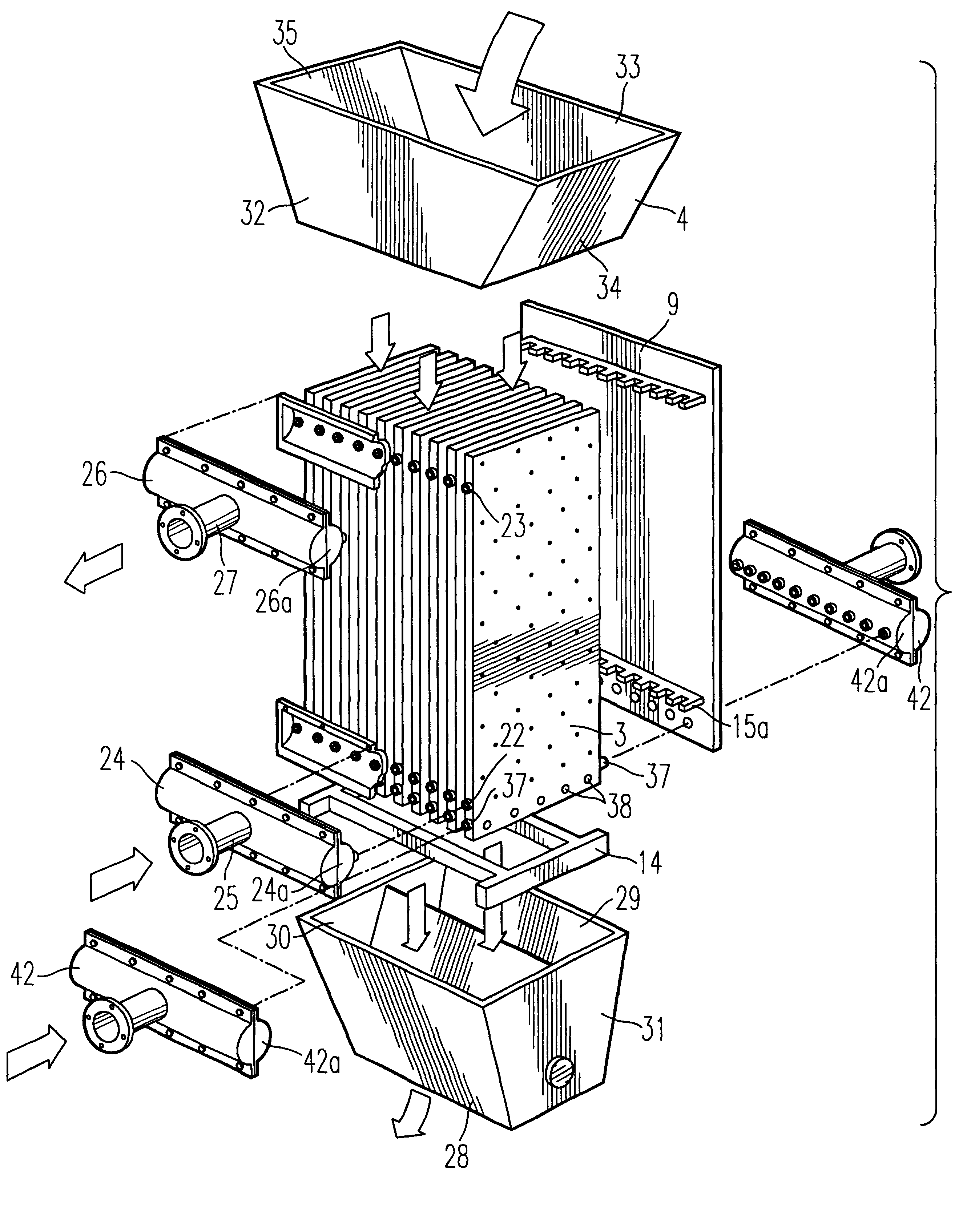
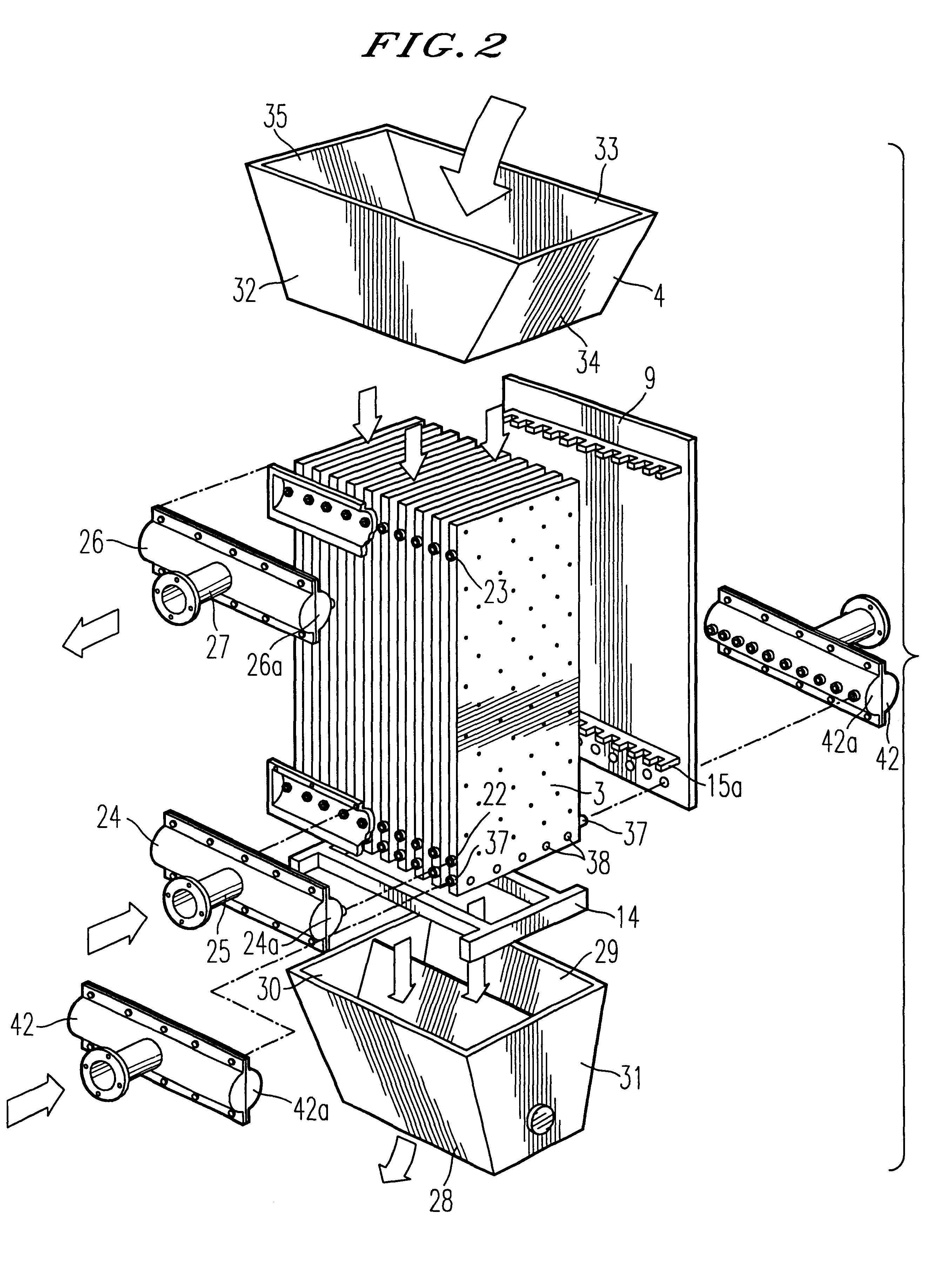
In FIGS. 1, 2 and 3 a moving bed dryer, generally indicated at 1, includes a housing 2 containing a multiplicity of heat exchanger plates 3, a feed hopper 4 and a discharge hopper 5. Feed hopper 4 and discharge hopper 5 are attached at the upper and lower extremities of housing 2 and have a common center line with the housing. The dimensions of the bottom opening of feed hopper 4, of the top opening of discharge hopper 5, and of the top and bottom openings of housing 2 are the same.
The housing 2 has a generally square or rectangular cross section and comprises a front panel 8, a back panel 9 and two side panels 10. Front panel 8 is attached to and between two corner posts 11 (angle irons). Side panels 10 are each attached to and between a corner post 11 and a corner post 12 (angle iron) such that one side of a corner post 12 is perpendicular to side panels 10 and forms a flange 13 which has means for the remo...
PUM
| Property | Measurement | Unit |
|---|---|---|
| thicknesses | aaaaa | aaaaa |
| width | aaaaa | aaaaa |
| gravity | aaaaa | aaaaa |
Abstract
Description
Claims
Application Information