Horizontally and vertically convertible connector for printed circuit boards

a technology of printed circuit boards and convertible connectors, applied in the direction of coupling device connections, ventilation systems, heating types, etc., can solve the problems of increasing the number of constituent parts, complex stock control, and raising the manufacturing cos

Inactive Publication Date: 2001-12-11
JST MFG CO LTD
View PDF7 Cites 25 Cited by
  • Summary
  • Abstract
  • Description
  • Claims
  • Application Information

AI Technical Summary

Problems solved by technology

This will not only raise manufacture cost and but also increase the number of constituent parts, noticeably rendering intricate the stock control of them.

Method used


Image

  • Horizontally and vertically convertible connector for printed circuit boards
  • Horizontally and vertically convertible connector for printed circuit boards
  • Horizontally and vertically convertible connector for printed circuit boards

Examples


Embodiment Construction

Now, some preferable embodiments of the present invention will be described referring to the drawings.

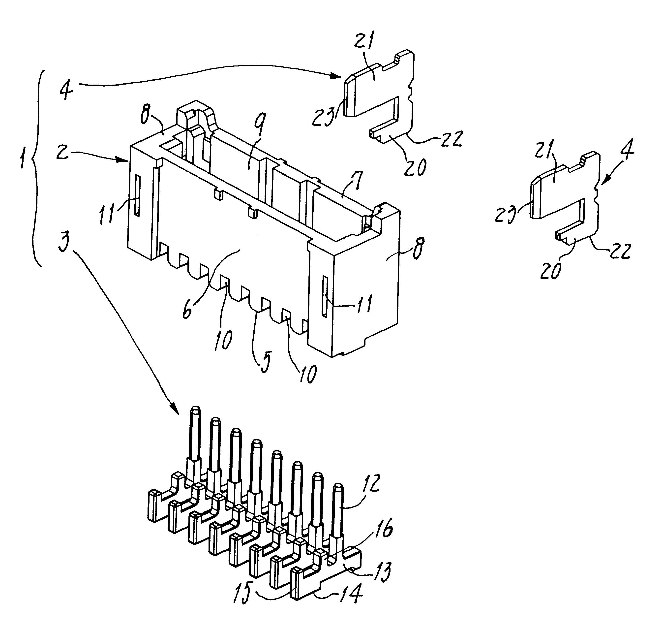
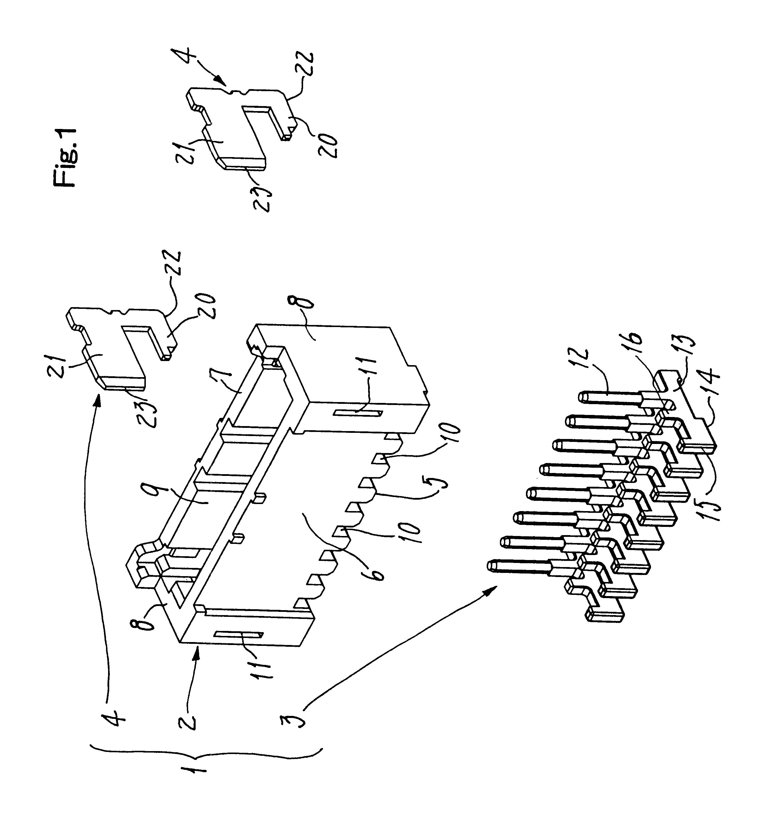
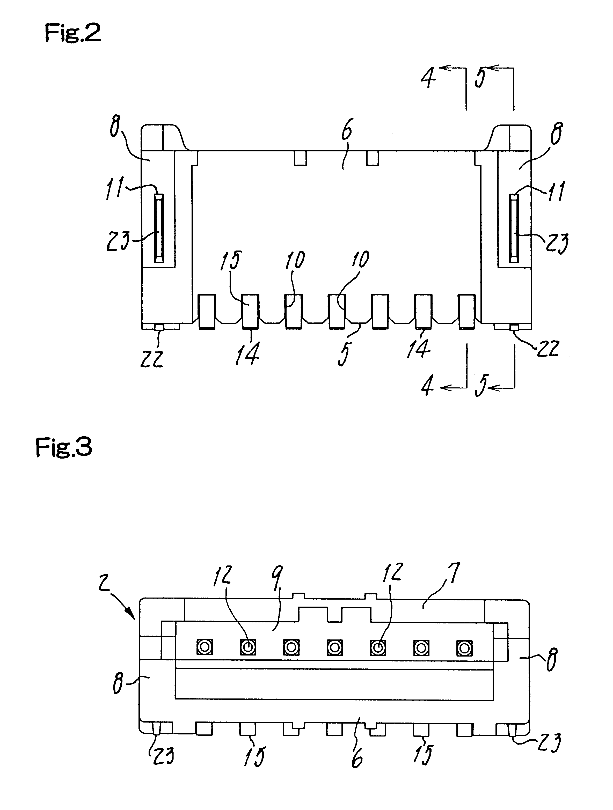
FIGS. 1 to 5 illustrate as a whole a connector 1 provided herein as a pin header for use with printed circuit boards. This connector 1 is composed of an insulated housing 2, a row of contacts 3 held at a regular pitch in the housing 2, and reinforcement metal pieces 4 that are fixed in both side ends of said housing.

The housing 2 is an elongate box made from an insulating material and having an opening facing upwards. The opening in the box is defined between a bottom 5, a front wall 6, a rear wall 7 and opposite lateral walls 8 and 8. The open top 9 of the housing serves as a connecting mouth for a mating connector (not shown). Groove-shaped cutouts 10 are formed at a constant pitch in the bottom 5 so as to respectively engage with the contacts 3. Apertures 11 and 11 are formed in the lateral walls 8 so as to receive and firmly hold therein the respective reinforcement metals 4.

The...


PUM


Abstract

A connector (1) for printed circuit boards (25) has an insulated housing (2), contacts (3) each with a lead (13) protruding from the contact to be soldered to a circuit pattern (26), and reinforcement metals (4) fixed in both sides of the housing and capable of soldering to a fixation pattern (27) on a board. These housing (2), contacts (3) and metals (4) are useful as they are, whether the connector takes a top type or a side type position. Each lead (13) and metal (4) respectively have first solderable portion (14) and zone (22) for top type position, and second solderable portion (15) and zone (23) for the side type position. The first portions and zones extend along the housing's bottom (5), the second portions and zones extending along the housing's front wall (6) or rear wall (7), such that the housing, contacts and metals need no change in shape between the top type and side type position so that the connector is made efficiently with reduced facility investment and with reduced sorts of its parts, lowering manufacture cost and facilitating stock control of parts.

Description

1. Field of the InventionThe present invention relates to a connector adapted for use with printed circuit boards and capable of being surface mounted thereon.2. Prior ArtThe known connector of this type for use with the printed circuit boards comprise each an elongate rectangular box as an insulated housing. The latter generally has an upper opened connecting portion for reception of conductive parts or elements leading to the circuit board. Leads integral with contacts held in the housing protrude outwards therefrom so as to be soldered to a circuit pattern printed on the board. Reinforcement metal pieces are fixed in the both sides of said housing are to be soldered to a fixation pattern that is also previously formed on each printed circuit board. Those prior art connectors are grouped into the so-called `top` type and the so-called `side` type. In the former type, a bottom of the housing will rest on the upper face of the printed circuit board so that the connecting portion ope...

Claims


Application Information

Patent Timeline
Patent Type & Authority Patents(United States)
IPC IPC(8): H01R12/16H01R12/32H01R12/36H01R12/00H01R12/22H01R13/66H01R12/57H01R12/71
CPCH01R12/57E03D9/052A47K13/307F24F7/06E03D11/02
Inventor FUJIKI, AKIHIKOUSHIRO, YUTAKAMASAKI, KATSUYUKI
Owner JST MFG CO LTD
Why Eureka
Try Eureka