Driving force control device for four-wheel drive vehicle

a four-wheel drive, torque control technology, applied in mechanical equipment, transportation and packaging, tractors, etc., can solve the problems of inability to obtain an objective, small torque transmission to the rear wheels, and increasing the weight of the vehicl

Inactive Publication Date: 2001-12-18
HONDA MOTOR CO LTD
View PDF7 Cites 23 Cited by
  • Summary
  • Abstract
  • Description
  • Claims
  • Application Information

AI Technical Summary

Problems solved by technology

If the difference in rotation between the front and the rear wheels is maintained so as to be small all the time, a tight brake phenomenon is caused when turning at a low speed causing the driver to feel uncomfortable and, moreover, it is necessary to increase the strength of the components used for transmitting the driving force between the front and the rear wheels, thus increasing the weight of the vehicle.
However, on a road surface hav...

Method used


Image

  • Driving force control device for four-wheel drive vehicle
  • Driving force control device for four-wheel drive vehicle
  • Driving force control device for four-wheel drive vehicle

Examples


Embodiment Construction

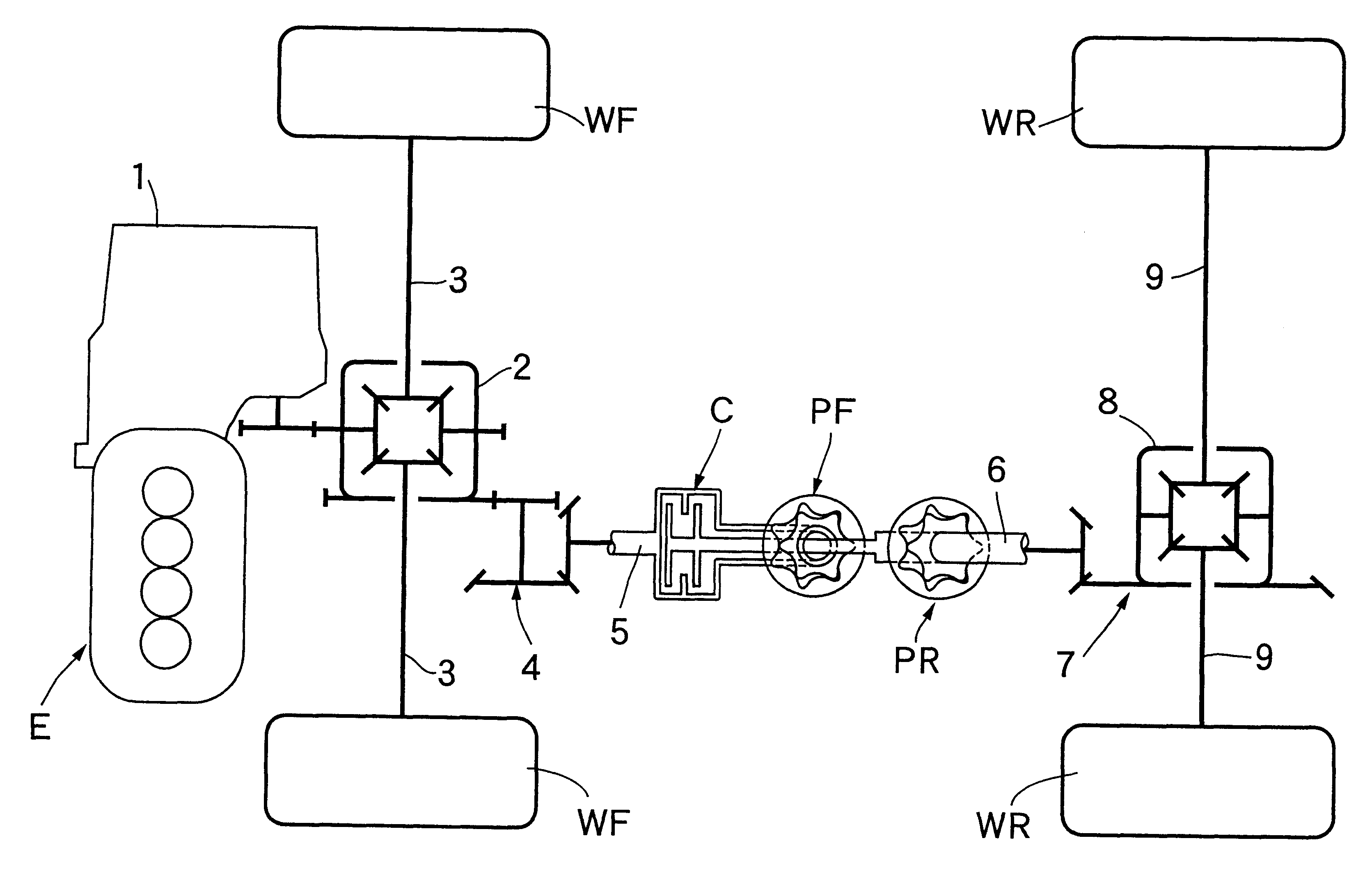
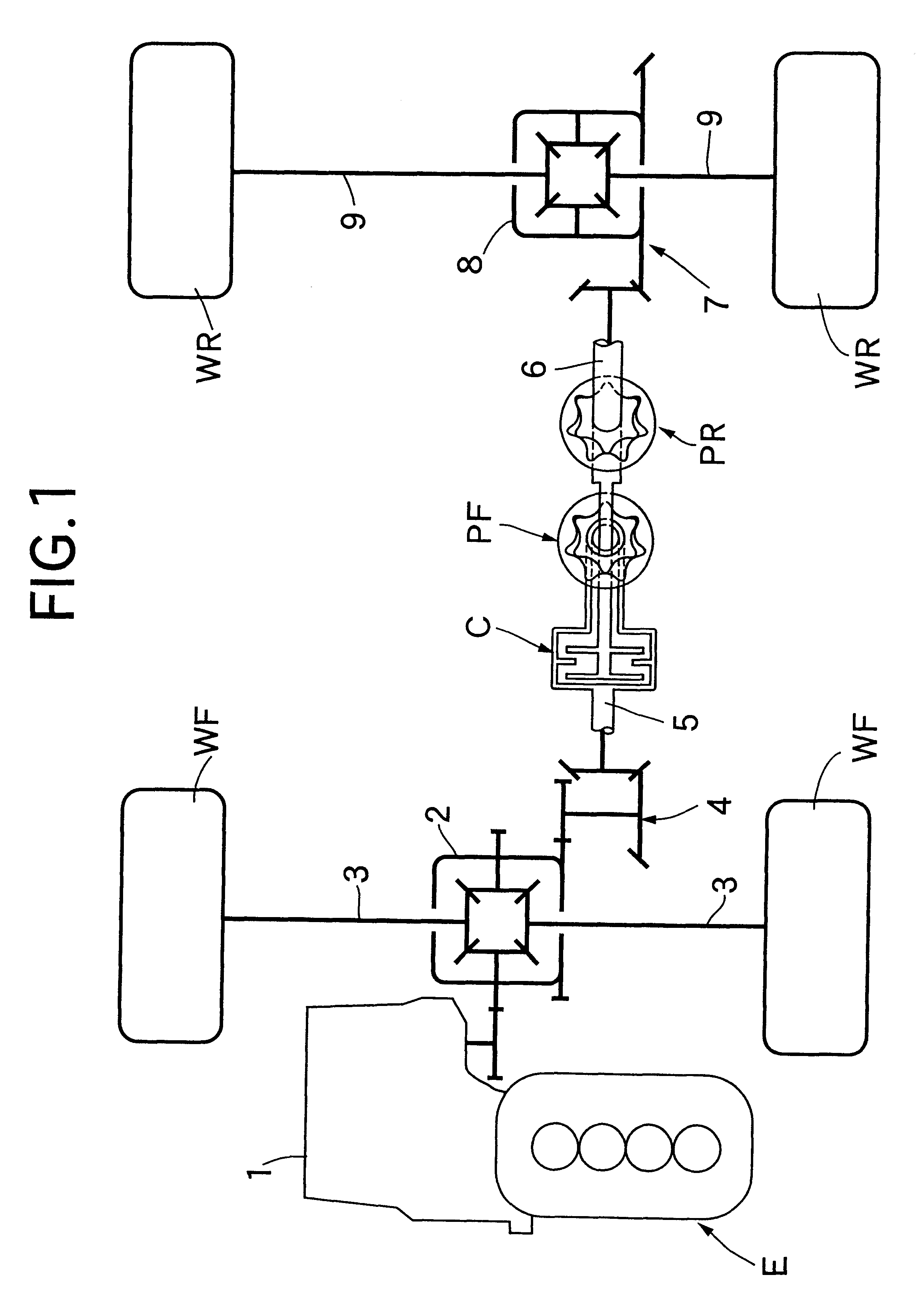
In FIG. 1 the output from an engine E as the prime mover mounted in the front part of a vehicle, is applied into a front differential 2 via a transmission 1. The output from the front differential 2 is transmitted to right and left front wheels WF, WF, which are driven wheels, via drive shafts 3, 3. Furthermore, the output from the engine E which has been applied to the front differential 2 is transmitted to an input shaft 5 of a hydraulic clutch C via a bevel gear 4 and the power output from an output shaft 6 of the hydraulic clutch C, is transmitted to right and left rear wheels WR, WR which are driven wheels via a bevel gear 7, a rear differential 8 and drive shafts 9, 9.

That is, while the right and left front wheels WF, WF, which are one pair of front or rear driven wheels, are driven directly by the engine E, the right and left rear wheels WR, WR which are the other pair of front or rear driven wheels, are driven via the hydraulic clutch C.

The engagement force of the hydraulic ...


PUM


Abstract

A driving force control device for a four-wheel drive vehicle including one pair of front or rear driven wheels which are driven directly by a prime mover and another pair of front or rear driven wheels which are driven via a hydraulic clutch, a first hydraulic pump which is driven by being operatively connected to the one pair of driven wheels, and a second hydraulic pump which is driven by being operatively connected to the other pair of driven wheels. The engagement force of the hydraulic clutch is controllable based on the difference in rotation of the first and second hydraulic pumps. The torque transmission to the other pair of the front or rear driven wheels can thus be controlled according to the driving conditions of the vehicle. The engagement force of the hydraulic clutch is controlled by an engagement force control unit by selecting from multiple engagement characteristics, in which the responsiveness of the torque transmitted by the hydraulic clutch is varied, according to the driving conditions of the vehicle.

Description

1. Field of the InventionThe present invention relates to four-wheel drive vehicles comprising a pair of front or rear driven wheels which are driven directly by a prime mover and another pair of front or rear driven wheels which are driven via a hydraulic clutch. A first hydraulic pump is driven by being operatively connected to the pair of driven wheels and a second hydraulic pump is driven by being operatively connected to the other driven wheels. The engagement force of the hydraulic clutch is controllable according to the difference in rotation between the first and the second hydraulic pumps.2. Description of the Prior ArtThe use of a two-wheel drive state using only one pair of front or rear driven wheels during normal travel is known in the art, and when a difference in rotation between the front and the rear wheels occurs both pairs of front and rear driven wheels are driven together so as to enhance the travel stability. If the difference in rotation between the front and ...

Claims


Application Information

Patent Timeline
IPC IPC(8): B60K17/35B60K23/08B60K17/348F16D25/0638F16D48/02
CPCB60K17/3505B60K23/0808
Inventor SEKIYA, SHIGENOBUMATSUO, HIROYUKITAKAHASHI, KEIICHIARAI, YASUNORI
Owner HONDA MOTOR CO LTD
Why Eureka
Try Eureka