Image forming method and image forming apparatus

a technology of image forming and forming method, which is applied in the direction of other printing apparatus, duplicating/marking methods, printing, etc., can solve the problems of reducing the density of images, reducing the glossing property of visible images, and discoloring or faded materials

Inactive Publication Date: 2001-12-25
CANON KK
View PDF16 Cites 38 Cited by
  • Summary
  • Abstract
  • Description
  • Claims
  • Application Information

AI Technical Summary

Problems solved by technology

Such methods, however, raise problems when the recording medium is to be preserved, in that the color materials may be discolored or faded due to operation of ozone or light or that bleeding or the like may occur due to contact with water.
There is also a problem that glossing property of the visible image cannot be obtained adequately because the color materials form the surface layer.
The apparatus, however, raises problems where the recording medium with a flattening layer and an ink reception layer is processed with heat and pressure as a flattening process right after the inks create visual images, such that image density is lowered, that the flattening layer is deformed, and that peeling or swelling or cracking of films may occur, since the ink solvent remains in the flattening layer or between the flattening layer and the ink reception layer.
Such an apparatus, however, raises problems such as its structure becomes complicated, manufacturing costs are increased, and the si

Method used


Image

  • Image forming method and image forming apparatus
  • Image forming method and image forming apparatus
  • Image forming method and image forming apparatus

Examples


second example of first embodiment

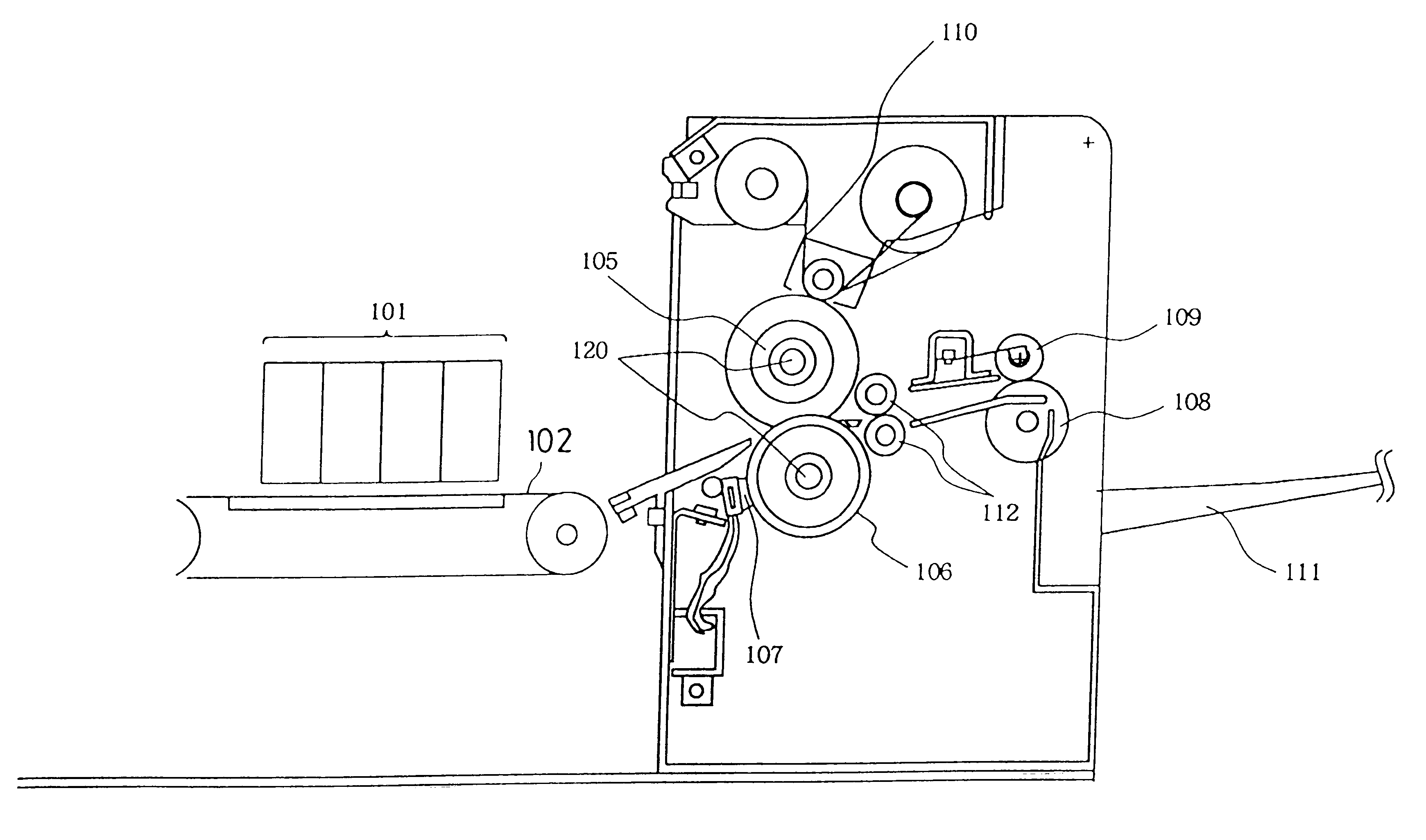
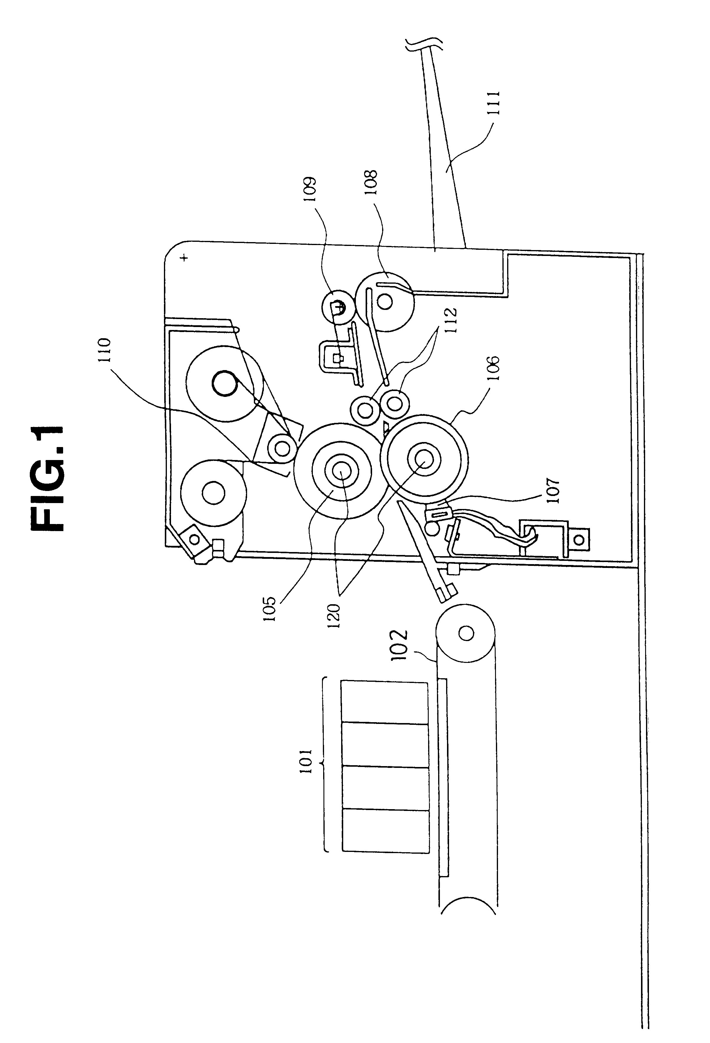
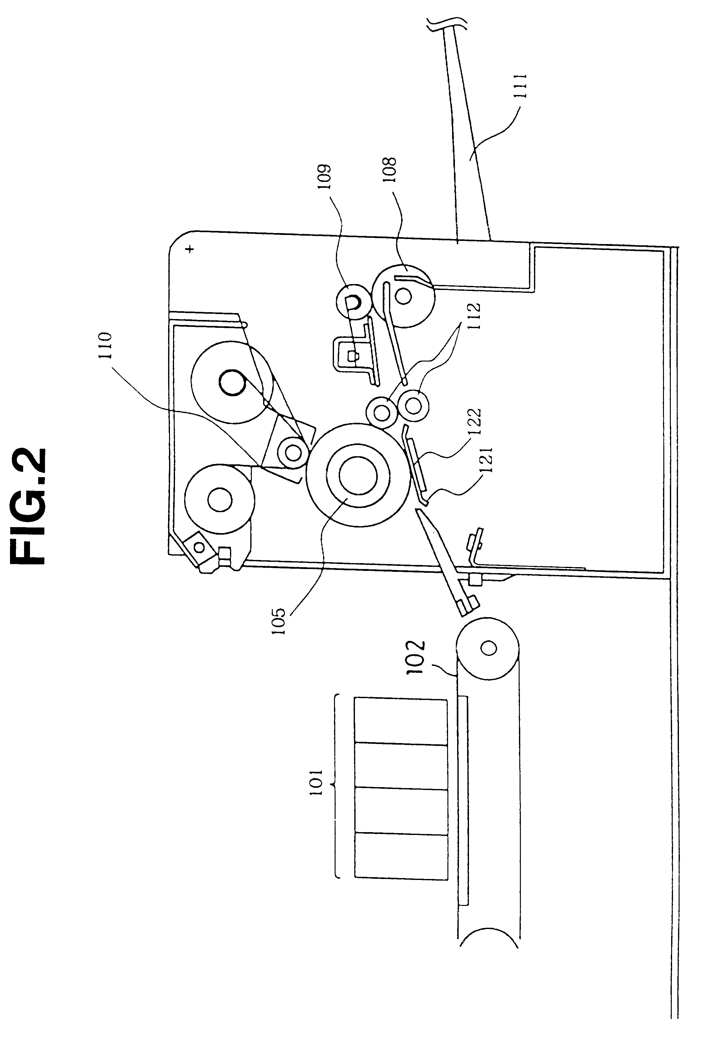
In this invention, the thermal pressing member in contact with a surface on which visible images are formed is workable as long as it operates at a speed equal to or less than a prescribed value and is also workable as long as the ink solvent component is adequately dried (or soaked into the reception layer) at a point where the thermoplastic layer (flattened layer) loses permeation nature in the nip region or the region upstream of the nip region. Accordingly, there is no particular limitation on the side of the non-recording surface of the recording medium. Therefore, as shown in FIG. 2, an iron plate or the like can be used for the non-recording surface side. In FIG. 2, a conveyance guide 121 opposing the upper heating roller 105 is a flat planar guide, and has a PTC heater 122 on the non-conveyance side. With this image forming apparatus of such a structure, a flattening process can be made by the upper heating roller 105 made of a silicon rubber as used in the above example, in...

third example of first embodiment

In this Example, the thermal pressing member has an inner layer made of rubber and a porous material and can be made as a belt. Now, an image forming apparatus having substantially the same structure shown in Example 1, but using such a thermal pressing member, will be described. FIG. 3 is a cross section showing an apparatus using a heating belt 300. The recording medium having images formed by a recording head 101 is conveyed to the flattening process by a conveyance roller 103 serving as a conveying means, sandwiched by a heating belt 300, which is wound around the heating plate 301 and the tension roller 304, and a pressing roller 30, and pressed with heat. The pressing amount is determined by a spring force that the pressing roller 306 pushes up from the lower side of the apparatus and by respective elastic forces. The temperature is set by a plate heater 301, which is disposed at the opposing position to the pressing roller 306 on the surface of the heating belt 300. The heati...

second embodiment

A second embodiment of the present invention will be described hereinafter. A method of this embodiment is for recording images on a transfer medium, not a recording medium of the first embodiment. Moreover, a transfer process of the second embodiment corresponds to the flattening process of the first embodiment, wherein in the transfer process, a transfer layer on which ink is disposed is transferred to a material to be printed.

The transfer medium used for the second embodiment of the invention is made of at least a base material and a transfer layer, which is a porous layer consisting of material such as resin and formed on the base material. The transfer layer is transferred to a material to be printed in a condition that porous construction is lost by heat melting after thermal transfer onto the material to be printed, and if the base material has a structure that the base material can be separated, a transfer medium previously known can be used. In this second embodiment, as di...


PUM

PropertyMeasurementUnit
Temperatureaaaaaaaaaa
Speedaaaaaaaaaa
Boiling pointaaaaaaaaaa

Abstract

The present invention relates to an image forming method comprising the steps of forming visible images in application of an ink, which at least includes an ink solvent and a color material, onto a recording medium having a porous layer on a surface of the medium from a side of the porous layer; conveying the recording medium from a location for forming images to a location for a subsequent process; and flattening the surface of the recording medium formed with visible images by pressing the surface while heating to form a flattened layer. In a nip region that the surface of the recording medium formed with visible images is pressed, a point A at which the ink solvent contained in the recording medium reaches the boiling point is located upstream of a point B at which the porous layer of the recording medium loses its liquid permeation property.

Description

1. Field of the InventionThis invention relates to an image forming method and an image forming apparatus for forming images using a recording section for recording visible images and a nip region for effecting a flattening process after the visible images are formed.2. Description of Related ArtA majority of known image forming methods form images by forming visual images using color materials such as dyes and pigments on a recording medium. Such methods, however, raise problems when the recording medium is to be preserved, in that the color materials may be discolored or faded due to operation of ozone or light or that bleeding or the like may occur due to contact with water. There is also a problem that glossing property of the visible image cannot be obtained adequately because the color materials form the surface layer. To treat with this problem, a method for flattening a sheet after recording is effective. Japanese Unexamined Patent Publication No. 4-21446 discloses an image ...

Claims


Application Information

Patent Timeline
IPC IPC(8): B41J11/00B41M5/00B41J2/01
CPCB41J11/002B41M7/00B41M7/009B41J11/0024B41J11/00242
Inventor HIGUMA, MASAHIKOTAKEKOSHI, NOBUHIKOKANEKO, HAJIMESUGAMA, SADAYUKI
Owner CANON KK
Why Eureka
Try Eureka