Method and apparatus for homogenizing drilling fluid in an open-loop process

a technology of open-loop process and method, which is applied in the direction of rotary stirring mixer, transportation and packaging, and wellbore/well accessories, etc., can solve the problems of inherently lost drilling fluid, high undesirable effects, and caving of wellbore holes

Inactive Publication Date: 2002-01-08
DIAMOND TANK RENTALS
View PDF14 Cites 10 Cited by
  • Summary
  • Abstract
  • Description
  • Claims
  • Application Information

AI Technical Summary

Problems solved by technology

However, during drilling operations, drilling fluid is inherently lost from the closed-loop designed drilling fluid system 1 and, thus, may need to be replenished.
As described, an adverse effect of an excessive filtration rate includes caving of the wellbore hole, which is highly undesirable, as a result of high water-loss muds.
The prior art Closed-Loop Preprocessors have proven to be unsatisfactory.
Thus, the Closed-Loop Preprocessor cannot provide a continuous "on demand" supply of drilling fluid.
It is estimated that approximately $50,000 are lost due to clogging of the filter/screen FS for a 4 or 5-day drilling operation and increased for longer drilling operations.
One of the biggest challenges in dissolving the undissolved polymer granules in the globs is that the globs stretch and deform when beaten, such as, by a propeller.
Since the known Closed-Loop Preprocessors are time consuming and have an inadequate throughput, typically, for offshore drilling, such as deep sea drilling, a start-up load of drilling fluid is pre-processed onshore and delivered to the offshore drilling rig site via a large (250 ft. plus) boat.
Not only are there costs associated with the transport of the initial start-up load of the processed drilling fluid, sea water or fresh water(the base) used to mix the drilling fluid may need to be hauled onshore for the processing of the drilling fluid.
The costs associated with the preprocessing of the drilling fluid, the transport of the pre-processed drilling fluid to the offshore drilling site and the costs associated with hauling the sea water or fresh water onshore for the initial load of the drill fluid still does not compare with the hourly costs associated with an operational drilling rig site.
Nevertheless, while great effort is taken for the creation of the init

Method used


Image

  • Method and apparatus for homogenizing drilling fluid in an open-loop process
  • Method and apparatus for homogenizing drilling fluid in an open-loop process
  • Method and apparatus for homogenizing drilling fluid in an open-loop process

Examples


Embodiment Construction

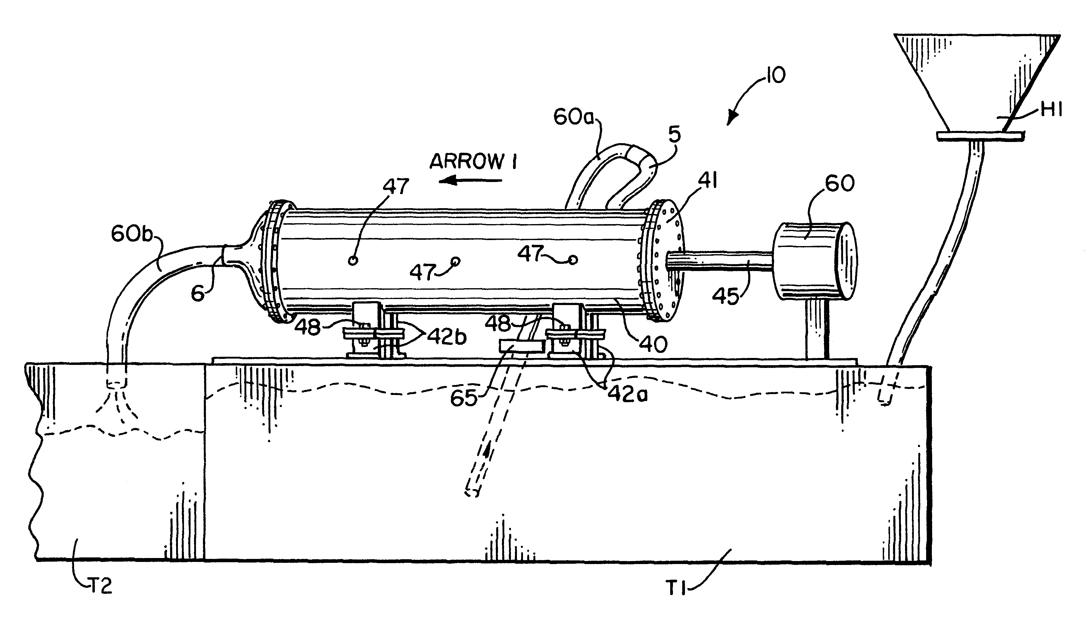
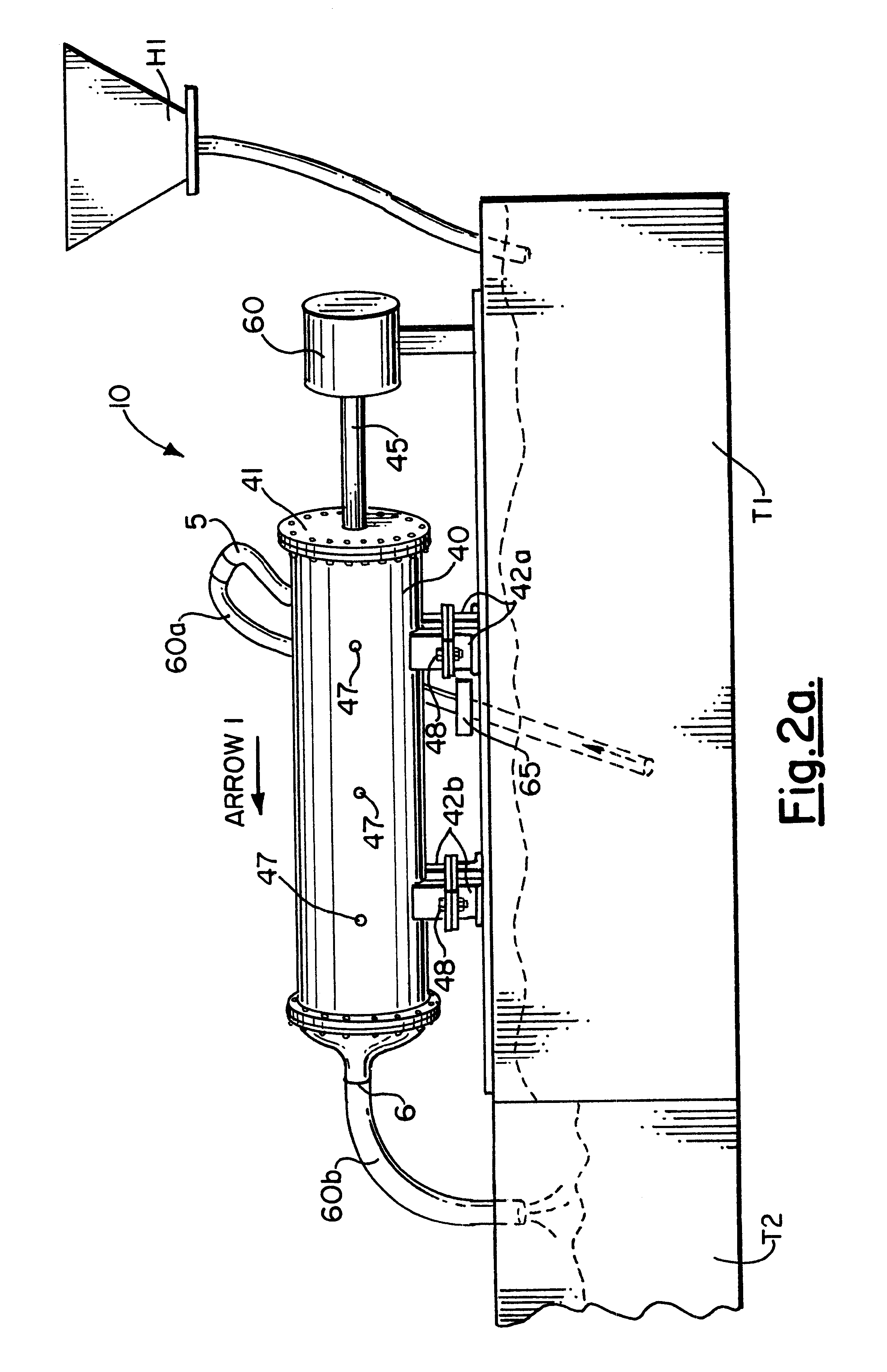
Referring now to the drawings, and in particular FIGS. 2a and 2b, the drilling fluid homogenizer of the present invention is designated generally by the numeral 10. In general, the homogenizer 10, of the present invention, comprises a homogenizing housing chamber or tubular pipe 40 and a homogenizing means 42 housed in the tubular pipe 40, for homogenizing, under pressure, in an open-loop process the drilling fluid for creating a non-clogging homogenized drilling fluid having substantially all glob sizes of globs of undissolved polymer granules less than or equal to a predetermined non-clogging glob size.

In the preferred embodiment, homogenizing means 42 includes a rotatable shaft 45 rotatably mounted along the axis of the tubular pipe 40 wherein the tubular pipe 40 is divided into a plurality of homogenizing classifying stages I, II, and III, in series, and which are in fluid communication. The plurality of homogenizing classifying stages I, II, and III homogenize the drilling flui...


PUM


Abstract

A drilling fluid homogenizer and method of homogenizing drilling fluid which produce a non-clogging homogenized drilling fluid at a high throughput, in an open-loop process. The non-clogging homogenized drilling fluid is capable of being created at high rate so that the non-clogging homogenized drilling fluid is available on demand to eliminate halting of drilling operations. The drilling fluid homogenizer is coupled in series with the closed-loop designed drilling fluid system and is adapted to homogenize water-based drilling fluid and other drilling fluid types, such as, synthetic drilling fluid during drilling operations on demand.

Description

DESCRIPTION1. Technical FieldThe present invention relates to methods and apparatuses for processing drilling fluids used in oilfield well drilling and, more particularly, to a method and an apparatus for homogenizing drilling fluid in an open-loop process. In general, the method and apparatus for homogenizing drilling fluid dissolve polymers and other additives to homogenize drilling fluid in an effort to eliminate clogging within the closed-loop designed drilling fluid system while simultaneously increasing the throughput of the homogenized drilling fluid for use in the closed-loop designed drilling fluid system.2. Background of the InventionIn the oilfield industry, when drilling a well, a lubricant termed "drilling fluid" or "drilling mud" (hereinafter referred to as "drilling fluid") is used. The major functions of the drilling fluid are to: (1) remove the drilled cuttings from the wellbore hole; (2) control the subsurface pressures; (3) cool and lubricate the bit and drill pip...

Claims


Application Information

Patent Timeline
IPC IPC(8): B01F13/00B01F13/10B01F5/06E21B21/06E21B21/00
CPCB01F5/0683B01F13/1041E21B21/062Y10S507/904B01F2013/108B01F25/451B01F33/83B01F33/83611
Inventor ADAMS, BEN A.COOPER, CHRIS G.
Owner DIAMOND TANK RENTALS
Why Eureka
Try Eureka