
Bicycle disc brake assembly

a disc brake and bicycle technology, applied in the direction of fluid-actuated brakes, cycle brakes, cycle equipment, etc., can solve problems such as the braking system

Inactive Publication Date: 2002-02-26
SHIMANO INC
View PDF19 Cites 31 Cited by
  • Summary
  • Abstract
  • Description
  • Claims
  • Application Information

AI Technical Summary

Benefits of technology

Another object of the present invention is to provide a disc brake assembly that is relatively compact and lightweight in relation to the amount of braking power.
Another object of the present invention is to provide a disc brake assembly that is relatively inexpensive to manufacture.

Problems solved by technology

However, one drawback to this type of braking system is that it is expensive because it requires a pair of pistons to move the end friction members towards the middle.
Another problem with prior double disc braking systems is that the caliper housing must be correctly aligned with the disc members of the rotor to avoid bending of the disc members.

Method used


Image

  • Bicycle disc brake assembly
  • Bicycle disc brake assembly
  • Bicycle disc brake assembly

Examples


Embodiment Construction

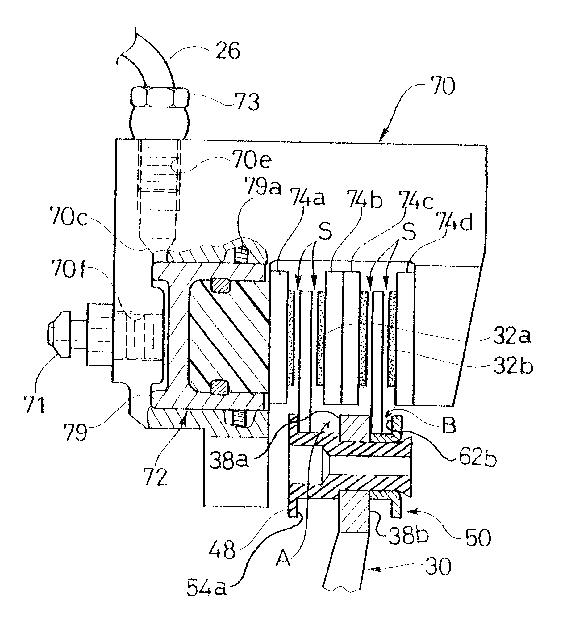
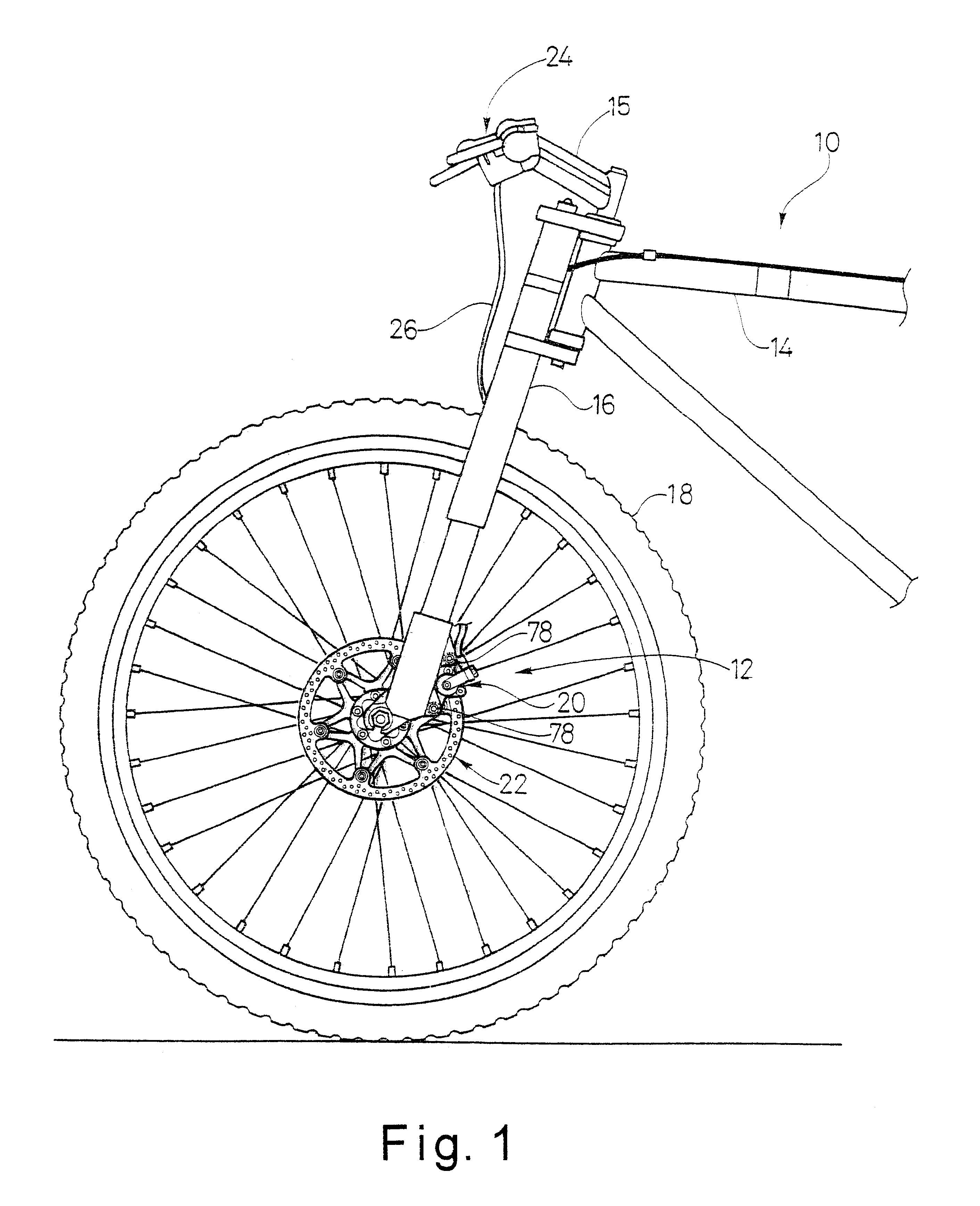
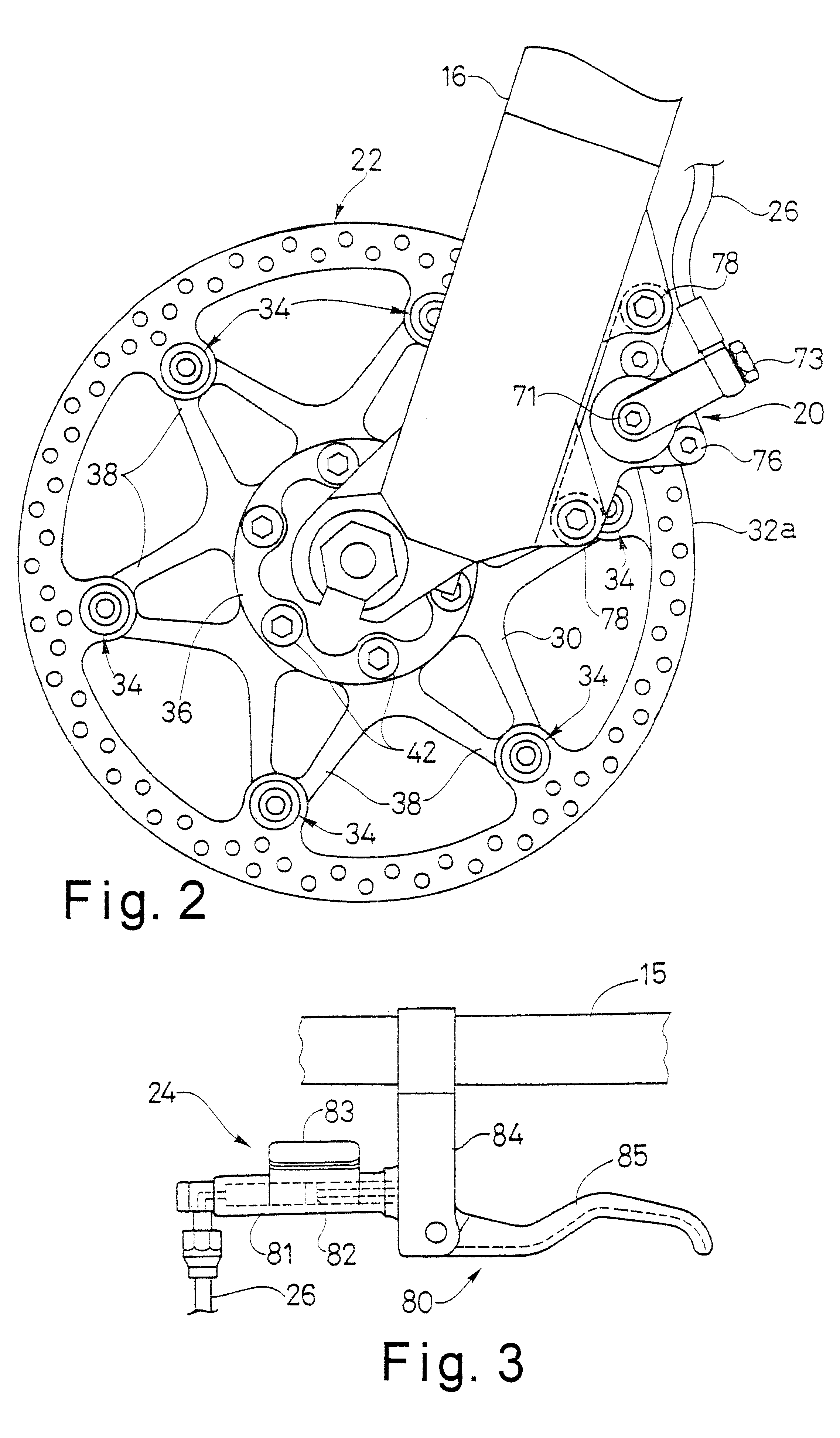
Referring now to FIG. 18, a disc brake assembly 112 is illustrated in accordance with a second embodiment of the present invention. The disc brake assembly 112 basically includes a disc brake caliper 120 and a disc brake rotor 122. The disc brake assembly 112 of the second embodiment is similar to the first embodiment, and thus, parts that serve the same function as those in the first embodiment have 100 added to the reference number. Disc brake assembly 112 is designed to be mounted on bicycle 10 of the first embodiment in substantially the same manner as the disc brake assembly 12 of the first embodiment. Moreover, disc brake caliper 120 is coupled to the brake operating mechanism 24 (FIG. 3) via hydraulic line or hose 26.

The disc brake caliper 120 is identical to disc brake caliper 20 discussed above, and thus, will not be discussed or illustrated in detail herein. Disc brake caliper 120 basically includes housing 170, a piston unit 172 and four friction members or pads 174a, 174...


PUM


Abstract

A bicycle disc brake assembly is provided with a double disc brake rotor with a pair of floating discs and a bicycle disc brake caliper with four friction members. The center or intermediate friction members are floating friction pads. The bicycle disc brake caliper also has a caliper housing with a single piston unit. The housing has a frame mounting member sized to be coupled to a portion of a bicycle frame. The piston unit is movably coupled to the housing between a release position, in which the piston unit is spaced from a disc brake mounted to a wheel of a bicycle, and a braking position, in which the piston unit engages the disc brake of the bicycle wheel. The double disc brake rotor has a support member with first and second disc brake members movably coupled thereto. More specifically, the support member has an outer attachment portion and an inner attachment portion. The inner attachment portion is configured to be coupled to rotate with a hub about a center rotational axis. The first disc member is movably coupled to the outer attachment portions for a first amount of axial movement relative to the support member. The second disc member is movably coupled to the outer attachment portion for a second amount of axial movement relative to the support member. The second amount of axial movement is different from the first amount of axial movement. Preferably, the first amount of axial movement is preferably at least twice the second amount of axial movement.

Description

1. Field of the InventionThis invention generally relates to disc brakes for bicycles. More specifically, the present invention relates to a disc brake caliper with a single piston unit that is used with a disc brake rotor having a pair of floating disc members.2. Background InformationBicycling is becoming an increasingly popular form of recreation as well as a means of transportation. Moreover, bicycling has become a very popular competitive sport. Whether the bicycle is used for recreation, transportation or competition, the bicycle industry is constantly improving their components. One particular component of the bicycle, which has been extensively redesigned over the past years, is the braking systems of bicycles. In particular, the braking power of the braking systems is constantly being increased.There are several types of bicycle brake devices, which are currently available on the market. Examples of some types of common bicycle brake devices include rim brakes, caliper brak...

Claims


Application Information

Patent Timeline
Patent Type & Authority Patents(United States)
IPC IPC(8): B62L3/02B62L1/00B62L3/00F16D65/12F16D65/14F16D55/24F16D55/40F16D69/00F16D55/00B60T1/06
CPCB62L1/005B62L3/023F16D55/40F16D65/12F16D2055/0062F16D2121/02F16D2065/1316F16D2065/132F16D2065/1364F16D2065/1392F16D2069/004F16D2055/007
Inventor NAKAMURA, YASUSHI
Owner SHIMANO INC
Learn More