Confocal laser scanning microscope, calibration unit for a confocal laser scanning microscope and method for calibrating a confocal laser scanning microscope

a laser scanning microscope and laser scanning technology, applied in the field of laser scanning microscopes, can solve the problems of shortened service life, intensity fluctuations, and substantial difficulties in calibrating systems, and achieve the effect of simple configuration of teaching

Inactive Publication Date: 2002-03-12
LEICA MICROSYSTEMS CMS GMBH
View PDF7 Cites 31 Cited by
  • Summary
  • Abstract
  • Description
  • Claims
  • Application Information

AI Technical Summary

Benefits of technology

According to the invention, it has become known that there is no sense in individually correcting and calibrating all the components of the system. Now then, it is possible using simple means to be able to calibrate a system of all or a multiplicity of the components simultaneously, in which case brightness fluctuations in the light source can be taken into account during detection. Such a calibration is possible by virtue of the fact that arranged in the plane of an intermediate image are appropriate calibration means which--like the object--can likewise be started or scanned by the scanning beam. Calibration is thereby possible during the actual recording and before and / or after scanning of the object.
In a particularly advantageous way, the calibration means can be pivoted into the region of the image field in the plane of the intermediate image. To this extent, the calibration means are put at the location of the intermediate image--into the image field. However, it is likewise also conceivable that the calibration means are arranged at the edge of the intermediate image outside the actual image field, it being possible for such an arrangement to be stationary. Mechanisms for moving the calibration means are not required in this case, with the result that this is a particularly simple configuration of the teaching according to the invention.

Problems solved by technology

However, when such systems are used for quantitative analyses, very substantial difficulties arise in calibrating the systems, specifically mostly whenever absolute intensities are to be measured.
Automatic light control of the laser leads as a rule to shortened service lives, specifically when maladjustments occur which are, in turn, compensated by a higher current.
A further problem arises as follows.
A further problem resides in that a monomode optical fiber can select different laser modes, as a result of which mode fluctuations of the laser can lead to intensity fluctuations.
Retroreflections in the lasers can disturb the internal laser control mechanisms, and thus lead to intensity fluctuations.
Finally, during rapid scanning of the beam with mirrors, inertial forces and control imperfections lead to deviations of the scanning beam from the desired path, specifically for the most rapidly scanned coordinates, in particular.
For practical reasons it is extremely complicated individually to correct and calibrate the participating components of the system.

Method used


Image

  • Confocal laser scanning microscope, calibration unit for a confocal laser scanning microscope and method for calibrating a confocal laser scanning microscope
  • Confocal laser scanning microscope, calibration unit for a confocal laser scanning microscope and method for calibrating a confocal laser scanning microscope

Examples


Embodiment Construction

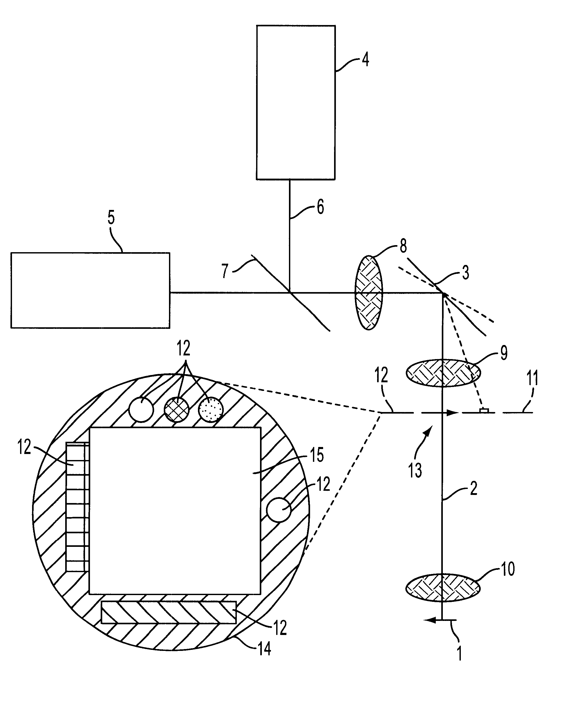
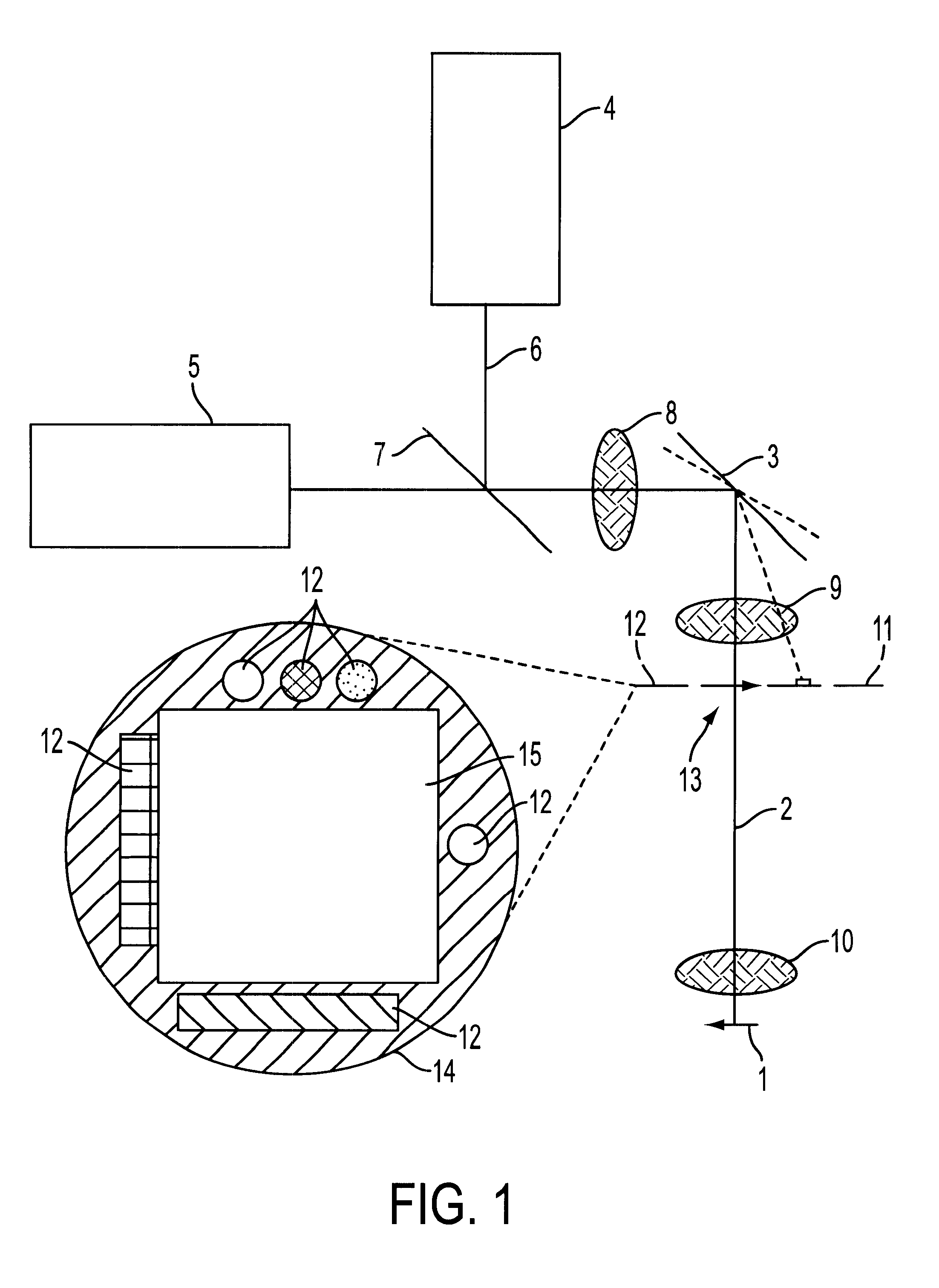
The sole figure shows a diagrammatic representation of an arrangement for calibrating a confocal laser scanning microscope, it being possible for an object 1 to be scanned by a scanning beam 2. For better comprehension of the teaching according to the invention, the figure shows not only the scanning beam 2 scanning the object 1, but the scanner 3, the laser light source 4 and the detector 5. The laser beam 6 is emitted by the light source 4, and passes via a beam splitter 7 via a suitable optical system 8 to the scanner 3. Starting from there, the scanning beam 2 is directed via an eyepiece 9 and an objective 10 to the object 1. Located between the eyepiece 9 and the objective 10 is an intermediate image 11, in the plane of which the calibration means 12 are arranged.

In the exemplary embodiment selected here, the calibration means 12 are arranged at the edge of the intermediate image 11 outside the actual image field 13. Provided for this purpose is a calibration template 14 which ...


PUM


Abstract

For the purpose of calibration which is simple and can also be carried out as often as desired, an arrangement and a method for calibrating a preferably confocal laser scanning microscope, it being possible for an object (1) to be scanned by a scanning beam (2), are defined by calibration means (12) which are arranged in the plane of an intermediate image (11) and can likewise be scanned by the scanning beam (2).

Description

The invention relates to an arrangement for calibrating a preferably confocal laser scanning microscope, it being possible for an object to be scanned by a scanning beam. The invention also relates to a corresponding method.RELATED ARTLaser scanning microscopes, but also in particular confocal laser scanning microscopes, are being applied ever more often to present microscopic objects. Because of the confocal arrangement, such systems are particularly well suited to three-dimensional images of structures, and lead to unusually good image qualities, particularly in the case of fluorescence photographs of thick samples. However, when such systems are used for quantitative analyses, very substantial difficulties arise in calibrating the systems, specifically mostly whenever absolute intensities are to be measured.The intensity of a laser can usually be modified by setting the tube current over a certain range. In the case of multiline lasers and mixed gas lasers, the mutual intensity r...

Claims


Application Information

Patent Timeline
Patent Type & Authority Patents(United States)
IPC IPC(8): G02B21/00
CPCG02B21/0024G02B21/0056G02B21/0052
Inventor ENGELHARDT, JOHANN
Owner LEICA MICROSYSTEMS CMS GMBH
Why Eureka
Try Eureka