Imaging system for an optical scanner

an optical scanner and imaging system technology, applied in the field of optical scanning systems, can solve the problems of more demanding specification and difficult to achieve specification in practi

Inactive Publication Date: 2002-03-12
PACKARD INSTR CO INC
View PDF15 Cites 117 Cited by
  • Summary
  • Abstract
  • Description
  • Claims
  • Application Information

AI Technical Summary

Problems solved by technology

A drawback to this approach is that such a specification may be quite difficult to achieve in practice.
Moreover, future improvements and developments in optical scanning systems may necessitate that the systems operate with even more excitation and emission wavelengths, requiring a multichroic beamsplitter having an even more demanding specification requirements.

Method used


Image

  • Imaging system for an optical scanner
  • Imaging system for an optical scanner
  • Imaging system for an optical scanner

Examples


Embodiment Construction

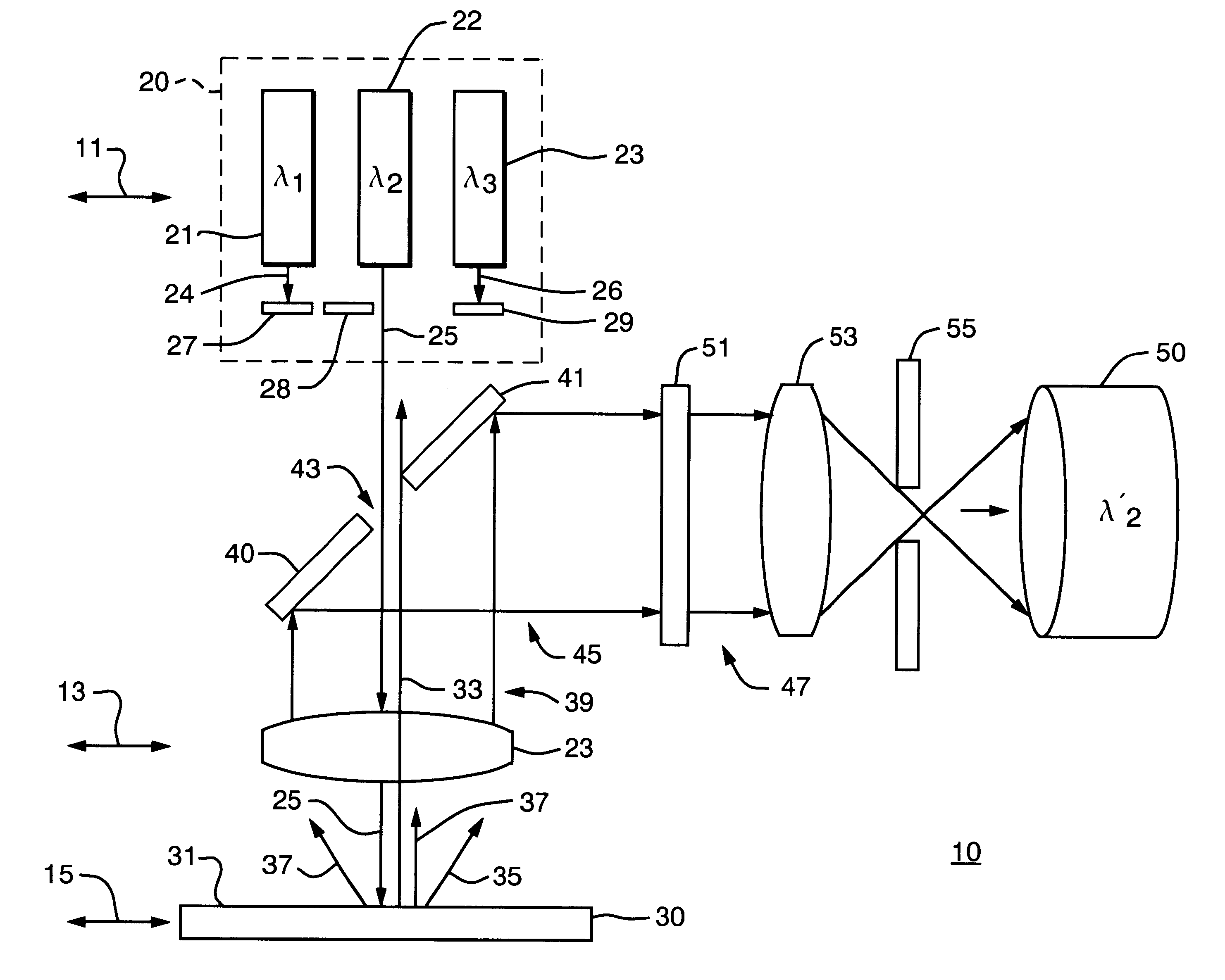
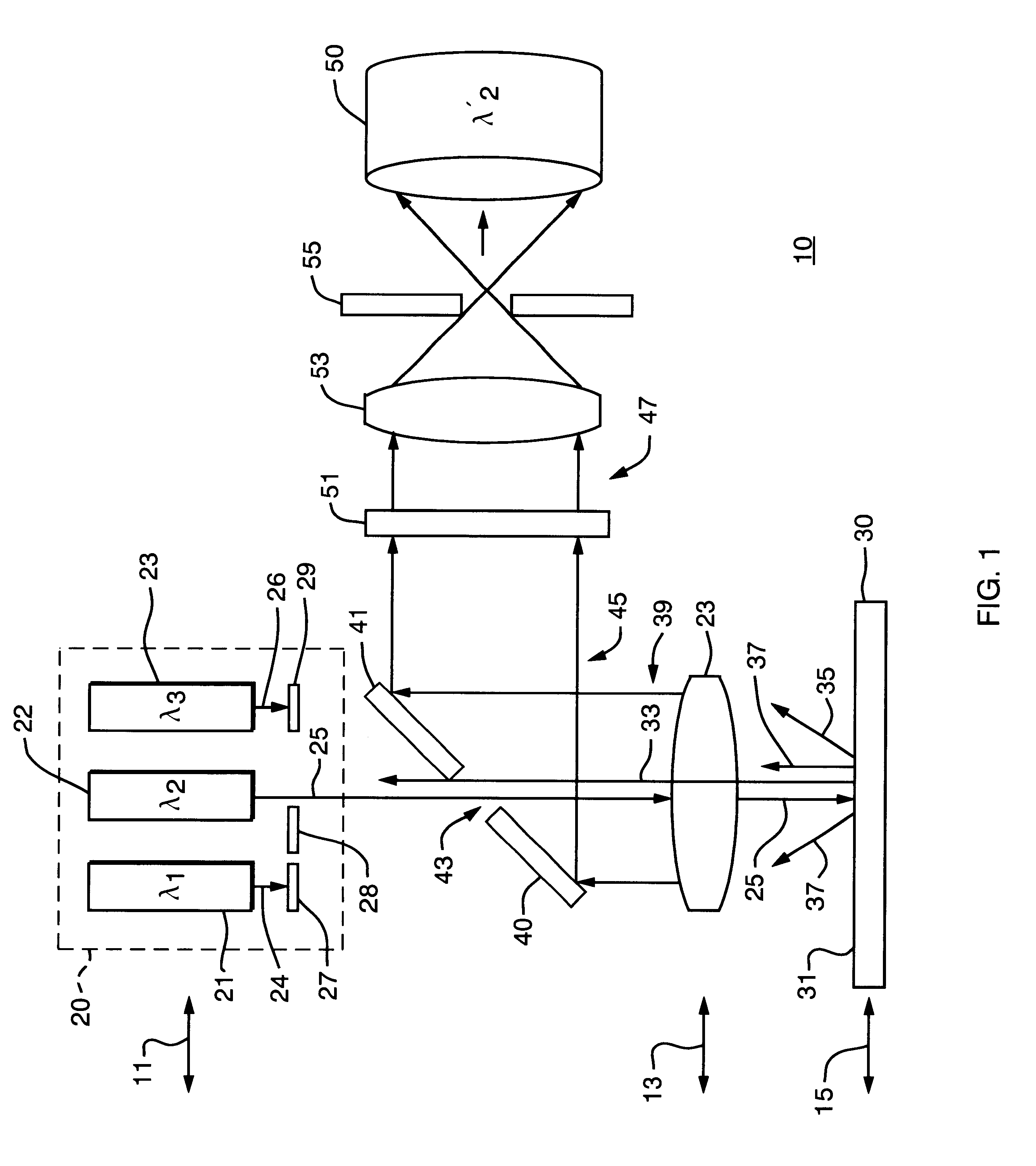
There is shown in FIG. 1 an imaging system 10, in accordance with the present invention, as can be utilized in the analysis of a sample 30. Imaging system 10 comprises an illumination array 20 comprising three radiation sources 21, 22, and 23, which can be laser devices or similar monochromatic optical sources, emitting, respectively, exitation beams of radiation 24, 25, and 26 having corresponding wavelengths .lambda..sub.1, .lambda..sub.2, and .lambda..sub.3, for illuminating sample 30. It should be noted that the present invention is not limited to only three radiation sources and additional sources can be used as desired. The illumination provided to sample 30 can be selected by powering only the radiation source(s) desired or, alternatively, radiation sources 21, 22, and 23 can be left in a powered state and one or more shutters 27, 28, and 29 can be moved into or out of the transmission paths of exitation beams 24, 25, and 26 to admit radiation of the desired wavelength and to...


PUM

PropertyMeasurementUnit
focal lengthaaaaaaaaaa
diameteraaaaaaaaaa
sizeaaaaaaaaaa

Abstract

An imaging system comprises three or more sources for providing excitation radiation of different wavelengths, an objective lens for focusing one or more of the exitation wavelengths onto a sample to produce fluorescent emission, and a mirror, configured as a geometric beamsplitter, disposed in the transmission path of the emission radiation and excitation radiation subsequent to reflection from the sample and collimation by the lens, wherein the mirror is utilized to reflect one of the collimated exitation and emission radiation such that the emission is directed to a detector and the collimated exitation is directed away from the detector.

Description

1. Field of the InventionThis invention in general relates to optical scanning systems and, in particular, to scanning systems such as fluorescent microarray readers, DNA micro-array readers, or "bio-chip" readers, in which exitation radiation of various wavelengths are used to produce fluorescence in a scanned sample.2. Description of the Prior ArtThe use of exitation radiation to produce fluorescence in a scanned sample is known. U.S. Pat. No. 5,381,224 issued to Dixon et al. discloses scanning optical imaging systems for macroscopic specimens, the system allowing both confocal and non-confocal imaging to be performed in reflected light. Fluorescent imagers are used to acquire data in experiments that utilize fluorescent labels to identify the state of a sample being tested. In some cases the presence of or lack of fluors in the sample determines the experimental result. In other cases the density of the fluors, a function of the intensity of the radiation emitted from the sample,...

Claims


Application Information

Patent Timeline
Patent Type & Authority Patents(United States)
IPC IPC(8): G01N21/64G02B21/00G02B21/16G02B21/36G06T1/00H04N1/04H04N1/113
CPCG01N21/6452G01N21/6458G01N2021/6419
Inventor OSGOOD, AVERYSCHERMER, MACK
Owner PACKARD INSTR CO INC
Why Eureka
Try Eureka