Diagnostic ionic flame monitor

Inactive Publication Date: 2002-03-12
ABB INC +1
View PDF6 Cites 32 Cited by
  • Summary
  • Abstract
  • Description
  • Claims
  • Application Information

AI Technical Summary

Problems solved by technology

This results in incomplete combustion due to a shortage of primary air.
Ignition systems are problematic pieces of equipment subject to a number of operational problems.
Typically, the electronic hardware cannot be adjusted and does

Method used


Image

  • Diagnostic ionic flame monitor
  • Diagnostic ionic flame monitor
  • Diagnostic ionic flame monitor

Examples


Embodiment Construction

)

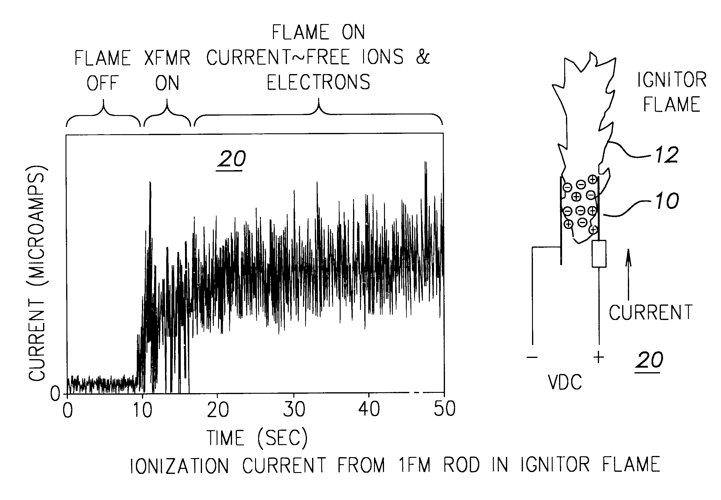
Referring now to FIG. 3, there is shown a diagram of the circuit 30 in the ionic flame monitor of the present invention that receives the output signal from the flame rod 10 of FIG. 1. As is shown in FIG. 3, the flame rod output signal enters circuit 30 through a relay 32 controlled by a microprocessor 40. In one state the relay 32 connects the flame rod output signal to circuit 30 and in the other state the relay 32 connects a test signal 34, to be described in more detail below, to circuit 30. The flame rod output signal passes through an amplifier 36 to a junction 38. Amplifier 36 has a gain which in the present embodiment for circuit 30 is manually adjustable in four steps in the normal mode of operation of the circuit 30 and under control of microprocessor 40 in a test mode of operation of circuit 30.

The signal at junction 38 enters a first path 42 which includes a low pass filter 44 between junction 38 and input 40c of microprocessor 40. The low pass filter 44 provides at the...


PUM


Abstract

An ionic flame monitor. The flame monitor has a flame rod that produces an ionization current when the flame rod is immersed in a flame and excited by a voltage. The ionization current has a DC component and an AC component each dependent on the intensity of the flame, and a flicker frequency. The flame monitor also has a computing device that is responsive to signals representative of the flicker frequency, and the AC and DC components of the ionization current for determining the existence of the flame.

Description

This invention relates to ionic flame monitors and more particularly to such a monitor that detects all of the characteristic components of the ionization current resulting from a flame.DESCRIPTION OF THE PRIOR ARTIonic flame monitoring (IFM) is a time proven method of detecting the presence of flame in fossil fuel combustion system. This particular technique for flame monitoring is primarily used for determining the existence of flame in oil and / or gas fired ignition system in industrial, utility, and commercial boilers.The ignition system is commonly referred to as an ignitor or lighter.One example of the use of ionic flame monitoring is described in U.S. Pat. No. 4,588,372 wherein a flame rod is used to monitor the flame in a gas burning furnace to maintain a peak flame rod current. This results in incomplete combustion due to a shortage of primary air. The furnace in that patent includes a secondary air inlet that is sized to maintain excess air in the combustion chamber for com...

Claims


Application Information

Patent Timeline
IPC IPC(8): F23N5/12
CPCF23N5/123F23N2029/12F23N2029/08F23N2229/08F23N2229/12
Inventor NIZIOLEK, JAMES M.CLARK, WILLIAM M.BIALOBRZESKI, JAMES M.GRAYSON, TERRY M.
Owner ABB INC
Why Eureka
Try Eureka