Universal coupling

Inactive Publication Date: 2002-03-19
METAULLICS SYST +1
View PDF13 Cites 117 Cited by
  • Summary
  • Abstract
  • Description
  • Claims
  • Application Information

AI Technical Summary

Benefits of technology

One advantage of the present invention is the provision of a coupling design that enables easy removal of a shaft stub which remains in a coupling member upon shaft failure.
Another advantage of the present invention is the provision of a coupling design that enables an operator to couple a shaft to a drive system in a quick and easy manner.
Another advantage of the present invention is the provision of a coupling design that provides optimal sealing properties for a degassing system.
Another advantage of the present invention is the provisi

Problems solved by technology

The straight thread design is a relatively weak coupling because the machining of the coupling causes stress risers in a ceramic or graphite shaft.
This results in an increased potential for shaft failure which is obviously undesirable.
Furthermore, when a shaft breaks, it typically breaks just below the coupling leaving little if any shaft extending from the coupling.
Thus, there is little material to work with in order to unscrew the stub.
In addition, because the resistance of the straight thread design is equal in both directions, it is extremely difficult to unscrew.
In other words, a significant amount of torque is required to remove the stub.
Removing the stub with a chisel and hammer causes additional problems.
The use of a chisel to remove the graphite stub may accidentally deform the threads in the coupling.
Such re-forming operations are time consuming and often result in shaft run-out.
Moreover, because graphite is a soft material, the normal replacement of the shaft in a straight thread design may lead to graphite deposit in the coupling threads, resulting in binding and shaft ru

Method used


Image

  • Universal coupling
  • Universal coupling
  • Universal coupling

Examples


Embodiment Construction

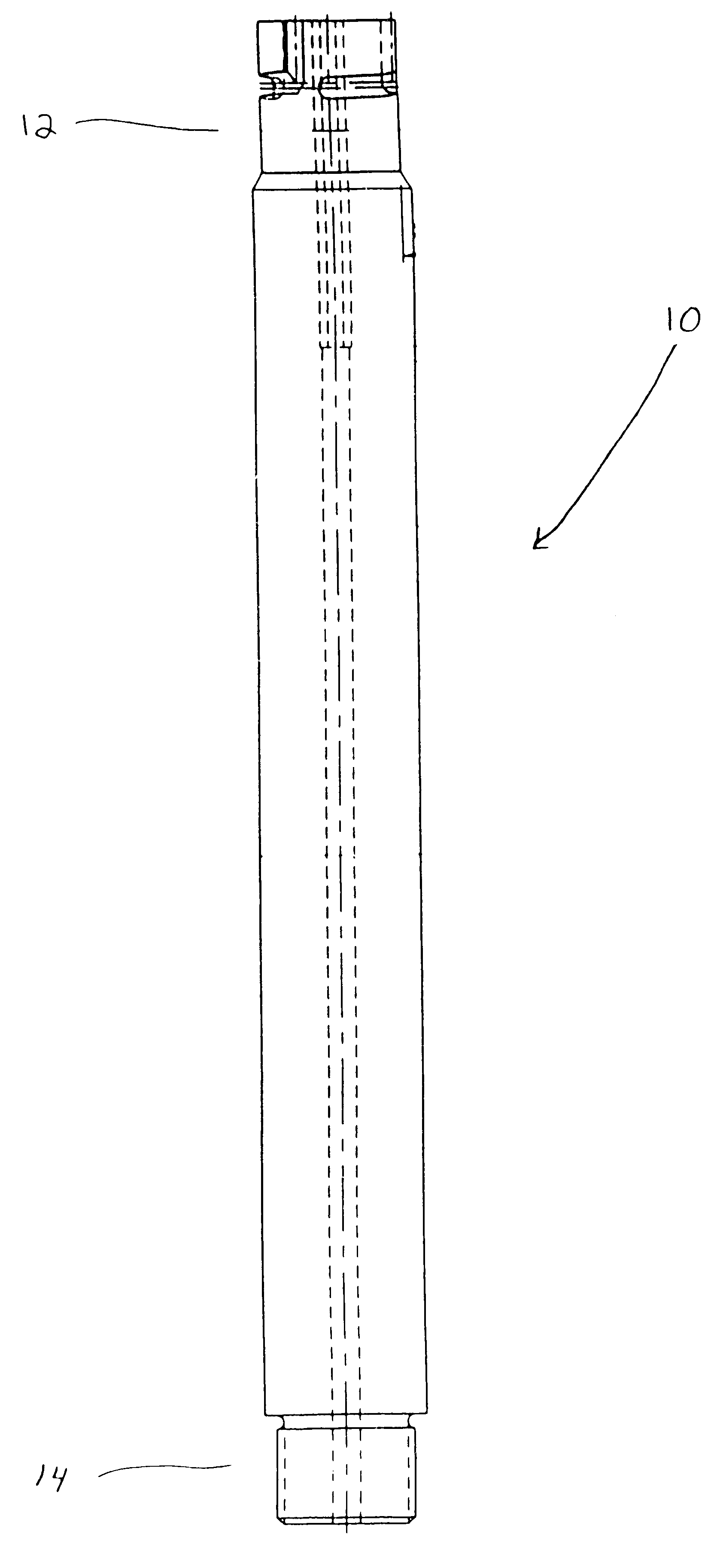
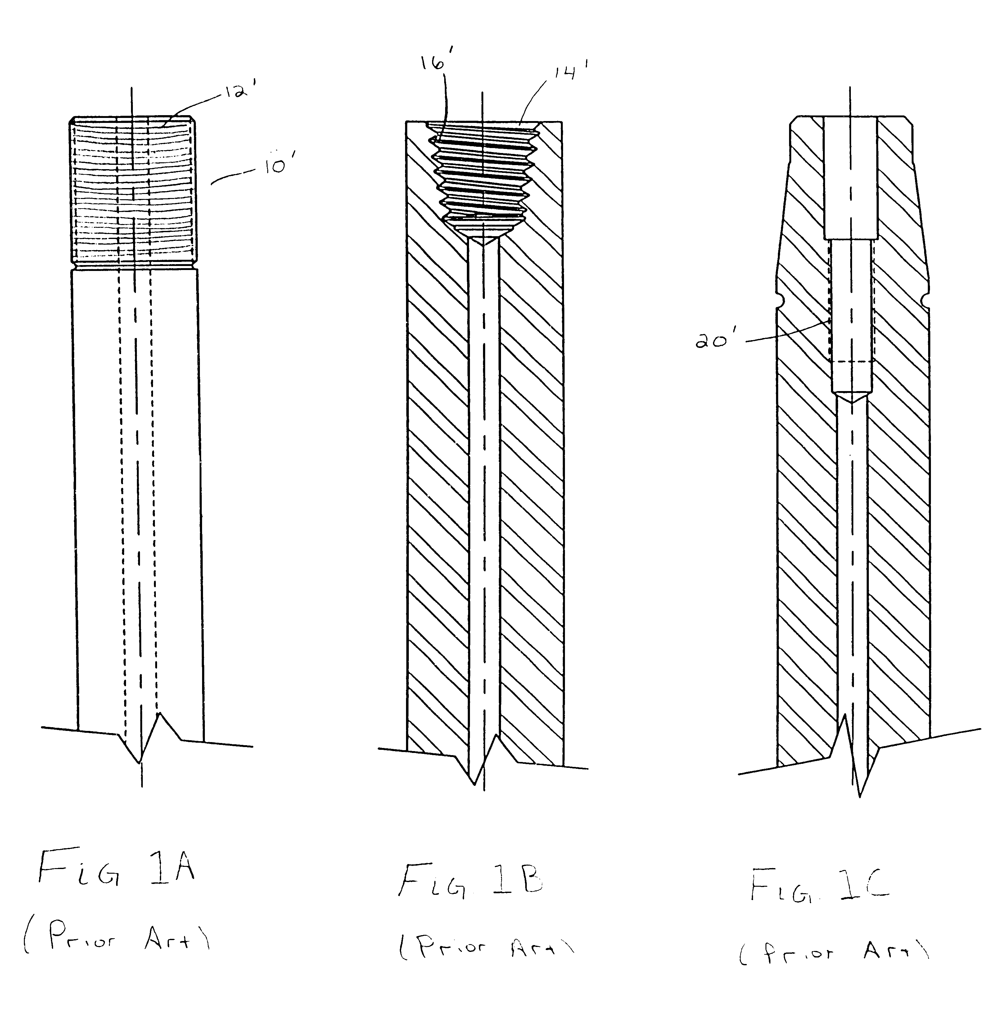
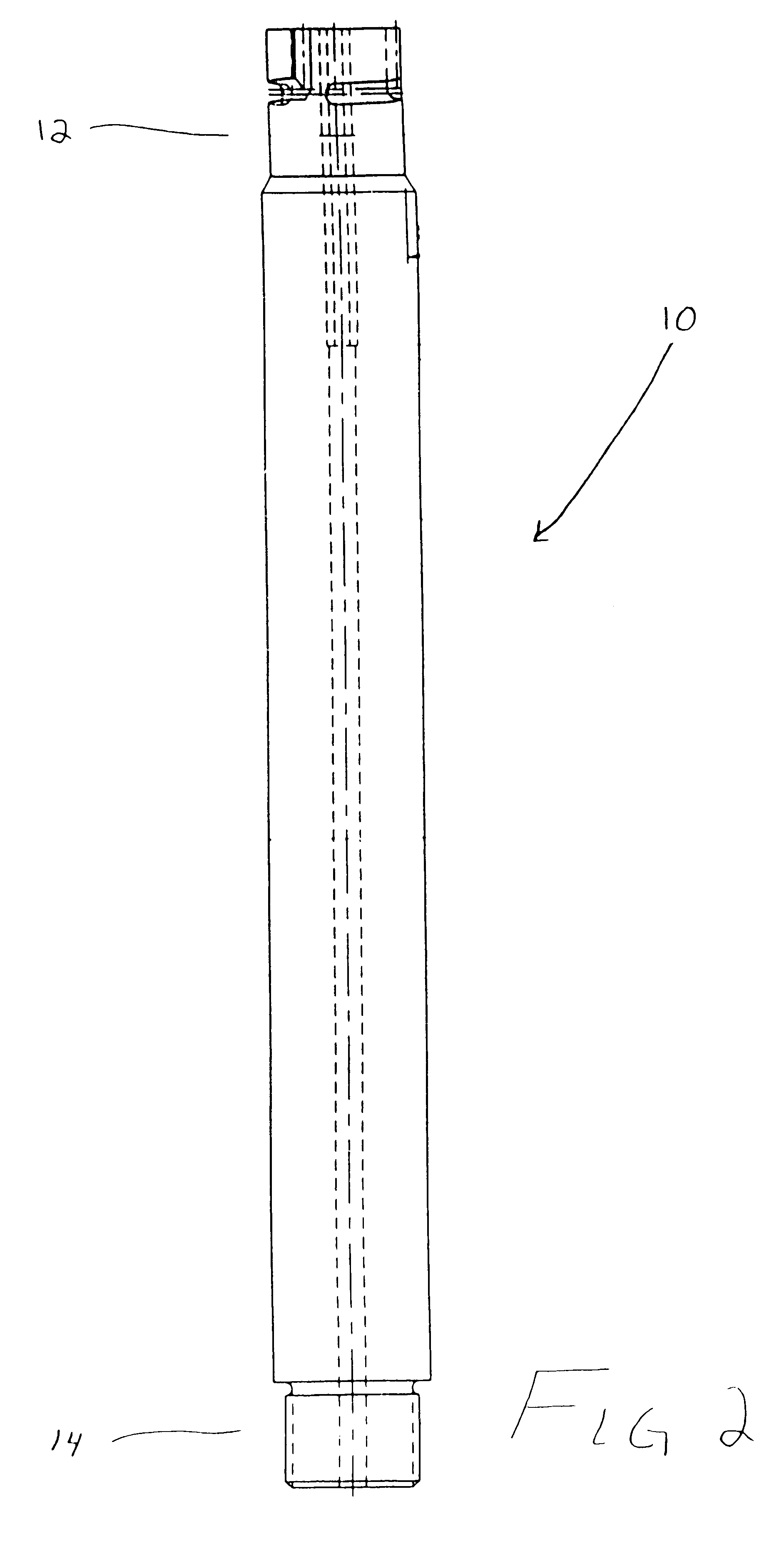
Reference will now be made in detail to the present preferred embodiment of the invention, an example of which is illustrated in the accompanying drawings. While the invention will be described in connection with the preferred embodiment, it will be understood that it is not intended to limit the invention to that embodiment. On the contrary, it is intended to cover all alternatives, modifications and equivalents that may be included within the spirit and scope of the invention defined by the appended claims.

The present invention is directed toward a coupling design for molten metal processing systems and is particularly well suited for degassing / flux injection applications. In operation, these systems inject argon, nitrogen, chlorine, fluxes and / or other appropriate gases or materials into a molten metal bath via an assembly consisting of a rotor connected to the lower end of a hollow shaft. The injected media removes dissolved gas such as hydrogen, may react with alkaline elements...


PUM

PropertyMeasurementUnit
Angleaaaaaaaaaa
Angleaaaaaaaaaa
Lengthaaaaaaaaaa

Abstract

A coupling mechanism for a molten metal processing system includes an elongated shaft having an upper axial end and a lower axial end. A passage having a torque facilitating shape extends through at least a portion of the shaft. The upper end of the shaft tapers inwardly and forms a tapered seat. At least one channel is machined into an outer surface of the upper end of the shaft. The channel has a first portion extending longitudinally downward from a top surface of the shaft and a second portion extending from the first portion at an angle greater than 90.degree. relative to the first portion. A coupling member, for coupling the shaft to a drive system, includes a body having an annular wall which defines a cavity. At least one locking member is disposed on an inner surface of the annular wall which is adapted to cooperate with the channel in the shaft. The locking member is aligned with the first portion of the channel and the shaft is slid into the cavity. When the locking member reaches a bottom surface of the first portion of the channel, the shaft is turned less than one third of a rotation so that the locking member travels partially across the second portion of the channel thereby pulling the shaft upward. The cavity of the coupling member tapers outwardly forming a mouth which engages the tapered seat of the shaft in a sealing relationship.

Description

BACKGROUND OF THE INVENTION1. Field of the InventionThis invention relates generally to the art of processing and treating molten metal. More particularly, this invention relates to a new and improved coupling design for a molten metal processing system.2. Discussion of the ArtMolten metal processing systems can usually be classified into several different types of systems. For example, degassing / flux injection, submergence and pumps are frequently used general categories.Systems which fall into the degassing / flux injection category generally operate to remove impurities from molten metal. More specifically, these systems remove dissolved metals, such as magnesium, release dissolved gases, such as hydrogen, from molten metal, and through floatation remove suspended solid impurites. In order to achieve these functions, gases or fluxes are introduced into a molten metal bath which chemically react with the impurities to convert them to a form (such as a precipitate or a dross) that ca...

Claims


Application Information

Patent Timeline
IPC IPC(8): B22D1/00C22B9/00C22B9/10C22B9/05F27D23/00C21C5/46F27D23/04F27D3/14C21C7/072F27D27/00F27D99/00
CPCB22D1/005C21C7/072F27D99/00C22B9/103C22B9/05C21C5/462F27D3/14F27D27/00
Inventor MORDUE, GEORGE S.
Owner METAULLICS SYST
Why Eureka
Try Eureka