

Cooling device boiling and condensing refrigerant
a technology of condensing refrigerant and cooling device, which is applied in the direction of cooling/ventilation/heating modification, semiconductor devices, basic electric elements, etc., can solve the problems of insufficient heat-transmitting performance between the heat-generating member and the heat-receiving wall of the refrigerant tank, insufficient cooling of the heat-generating member, and insufficient heat-transmitting performance between the heat-generating member and the heat-receiving wall
- Summary
- Abstract
- Description
- Claims
- Application Information
AI Technical Summary
Benefits of technology
Problems solved by technology
Method used
Image

Examples
first embodiment
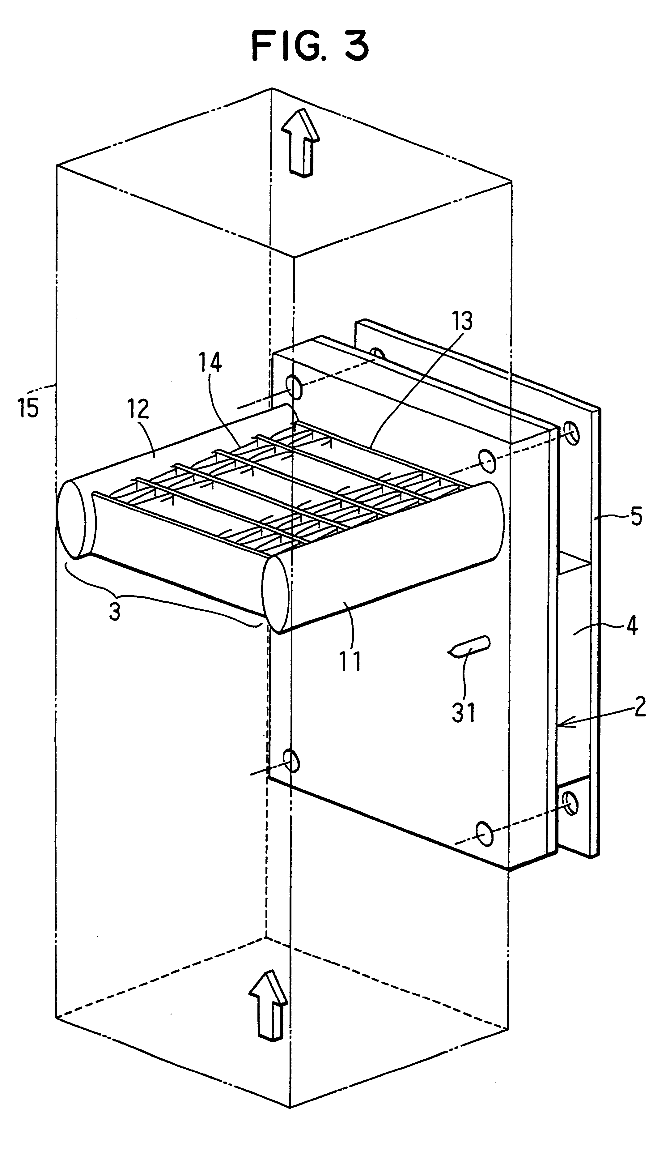
As shown in FIG. 3, the refrigerant tank 2 is used in an approximately vertical state. A CUP 4, which is a heat-generating member in the first embodiment, contacts one side surface of the refrigerant tank 2 in a thickness direction of the refrigerant tank 2. The refrigerant tank 2 is fixed by a bolt and the like to a printed base plate 5 onto which the CUP 4 is attached.
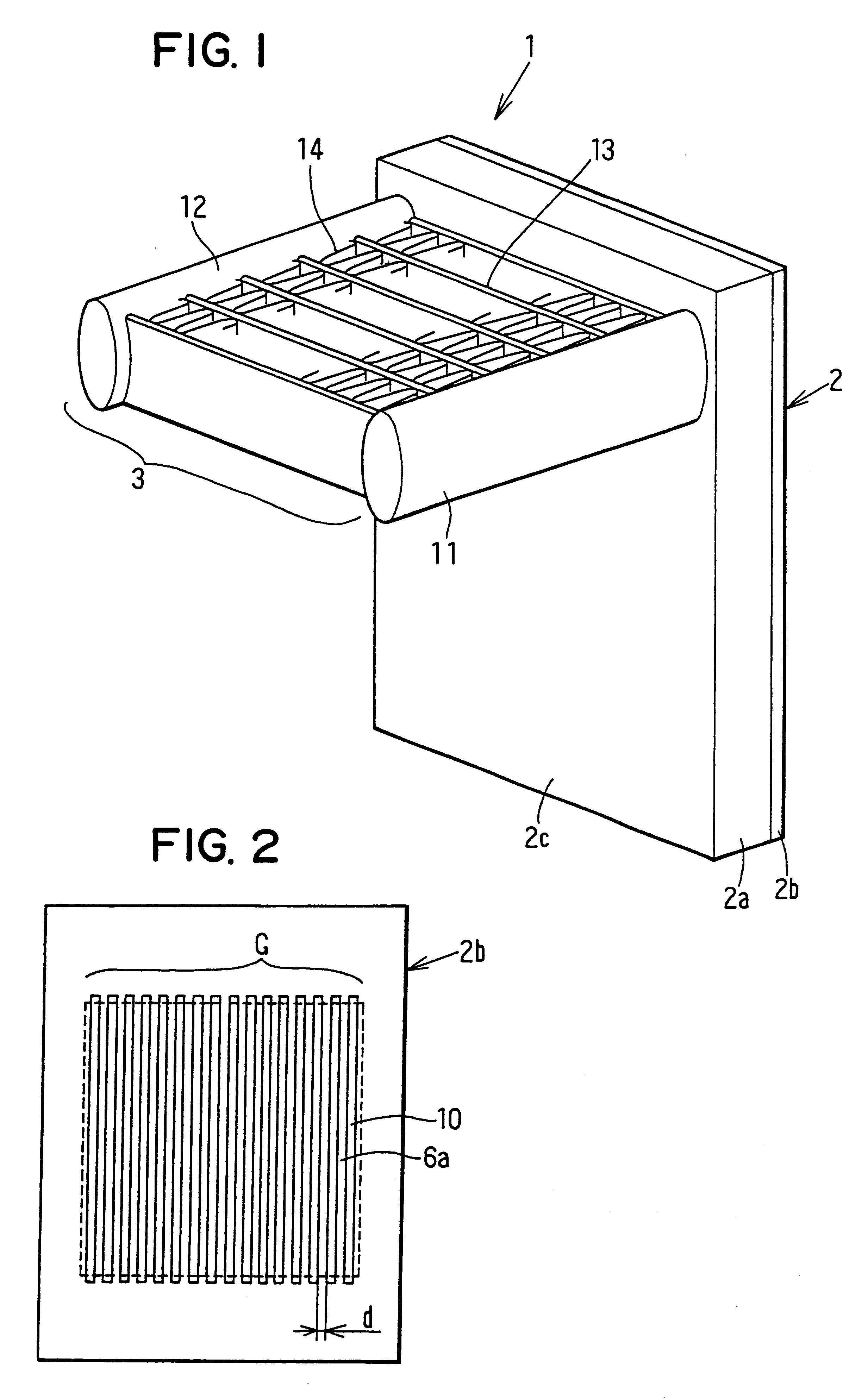
As shown in FIG. 4, the refrigerant tank 2 has therein a refrigerant chamber 6, a pair of header connection ports 7, a liquid-refrigerant returning passage 8 and a refrigerant inlet portion 9. The refrigerant chamber 6 is disposed at a position corresponding to the attachment portion of the CPU 4 to define a space in which liquid refrigerant is stored. That is, the attachment portion of the CPU 4 corresponds to a boiling surface of the refrigerant tank 2. As shown in FIG. 1, the refrigerant chamber 6 has a group structure G in which plural recesses are formed by plural ribs 10 provided on the cover plate 2b. Each top...
fifth embodiment
Next, operation of the cooling device will be now described. Heat generated by the heat-generating member 4 is transmitted into the refrigerant tank 2 from the attachment surface 23a, so that liquid refrigerant 27 around inside the heat-receiving wall 23 is boiled. Boiled gas refrigerant flows into the radiator 3, and is cooled and condensed in the radiator 3 to become the liquid refrigerant. Liquid refrigerant returns the refrigerant tank 2, and repeats the evaporation operation and the condensation operation.
In the fifth embodiment of the present invention, the connection members 23b can be provided to correspond to the ribs 10 of the above-described first embodiment. In this case, the same effect as the above-described first embodiment can be also obtained.
In the above-described fifth embodiment of the present invention, the sectional shapes of the connection members 23b and the porous layer 24 can be changed as indicated in FIGS. 15A-15E, for example. As shown in FIG. 15A, a se...
sixth embodiment
As shown in FIG. 18, the refrigerant tank 2 includes a refrigerant chamber 6 (boiling space) in which refrigerant is boiled by heat from the CUP 4 attached onto the attachment position 4a of the flat surface of the refrigerant tank 2, first header connection portions 38a, 39a, second header connection portions 38b, 39b, and a communication passage 30 through which the first and second header connection portions 38b, 39b at the left side in FIG. 18 communicate with each other. The refrigerant chamber 6 is provided so that heat from the CUP 4 is readily transmitted to refrigerant within the refrigerant tank 2. In the sixth embodiment, the refrigerant chambers 6 are partitioned by plural ribs (not shown) into plural passages extending in up-down direction.
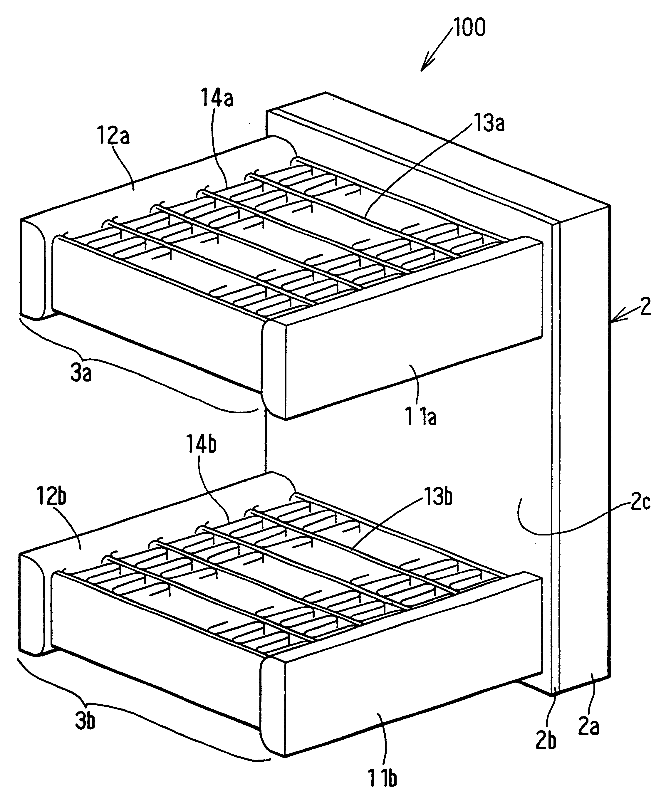
The first header connection portions 38a, 39a of the refrigerant tank 2 are respectively connected to first and second headers 11a, 12a of the first radiator 3a, and the second header connection portions 38b, 39b of the refrigerant ta...
PUM
 Abstract
Description
Claims
Application Information