Method of component manufacture

Inactive Publication Date: 2002-04-16
CRIMSON INT ASSETS LLC
View PDF8 Cites 120 Cited by
  • Summary
  • Abstract
  • Description
  • Claims
  • Application Information

AI Technical Summary

Benefits of technology

Those advantages that are primarily afforded by a method according to the present invention reside in the ability to produce in a cost effective manner components whose manufacture require a three-dimensional structure that can only be obtained by a micromechanical working process and where the components include physical measurements that only permit one or a few components to be produced with each substrate plate when practising traditional techniques.
This method opens the possibility of producing components that have hitherto been considered too costly in relation to what the components can achieve. The method therewith also opens a completely new field for the manufacture of components that enables components to be produced that have hitherto never been produce

Problems solved by technology

However, these conditions do not always apply, such as when certain physical measurements must be observed for instance.
In these cases, the combination of space-demanding or area-demanding funct

Method used


Image

  • Method of component manufacture
  • Method of component manufacture
  • Method of component manufacture

Examples


Embodiment Construction

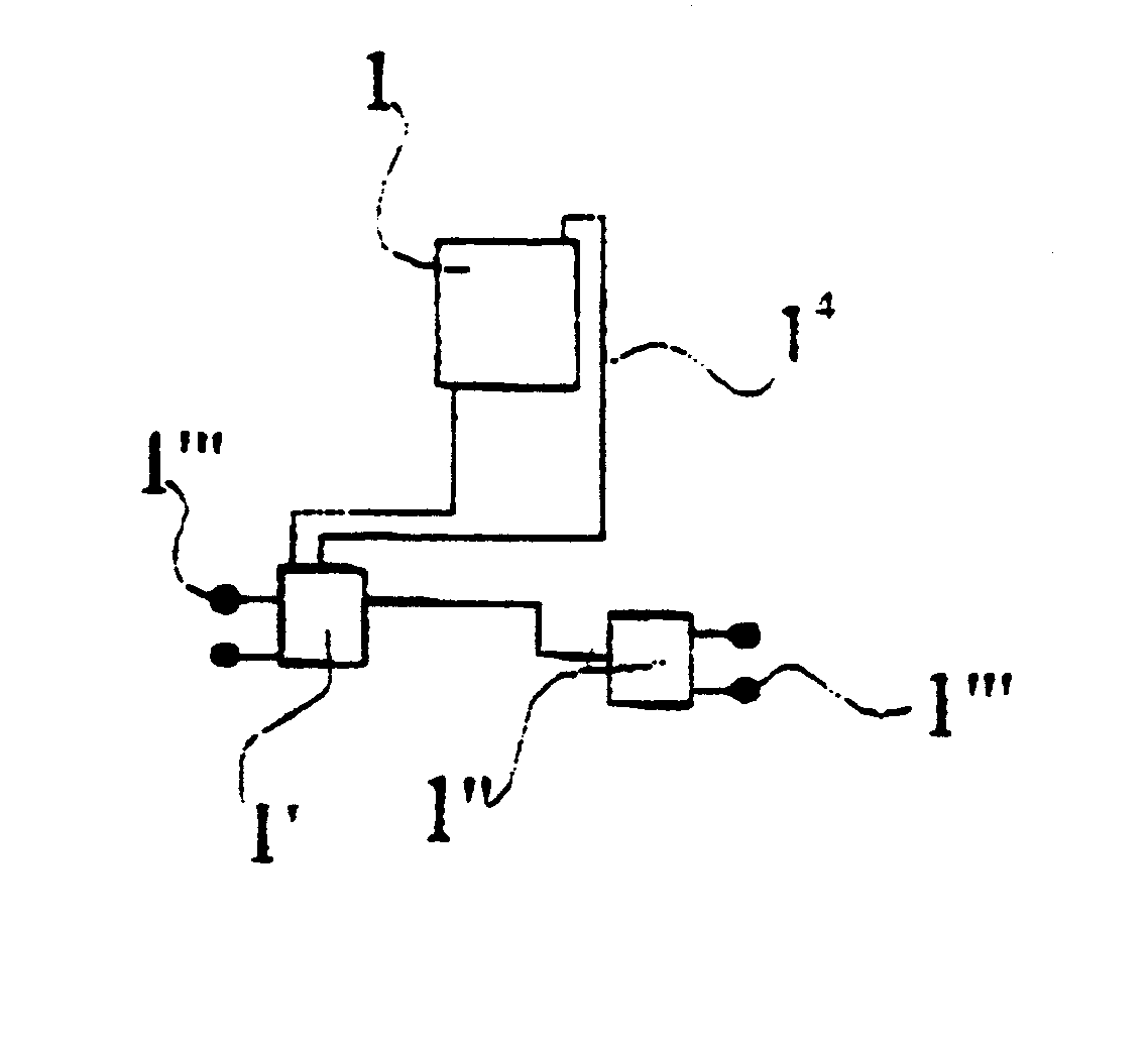
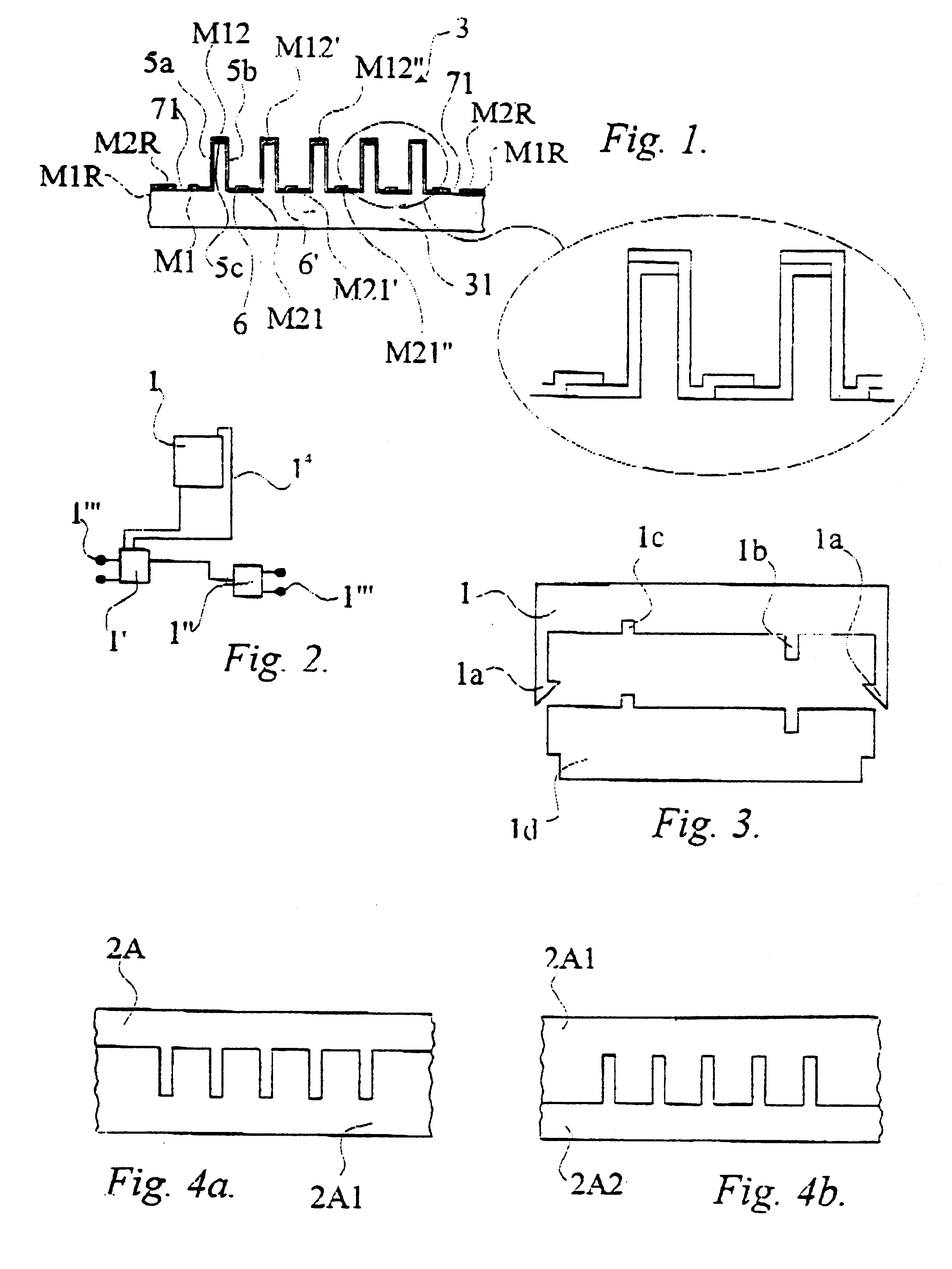
FIG. 1 thus shows a method of producing an electric, electronic optical and / or mechanical component.

The description is directed to a thermocouple 1 as an example of a component produced in accordance with the method. Reference is made to Swedish Patent Application 98 00462-5 for a more detailed description of such a thermocouple.

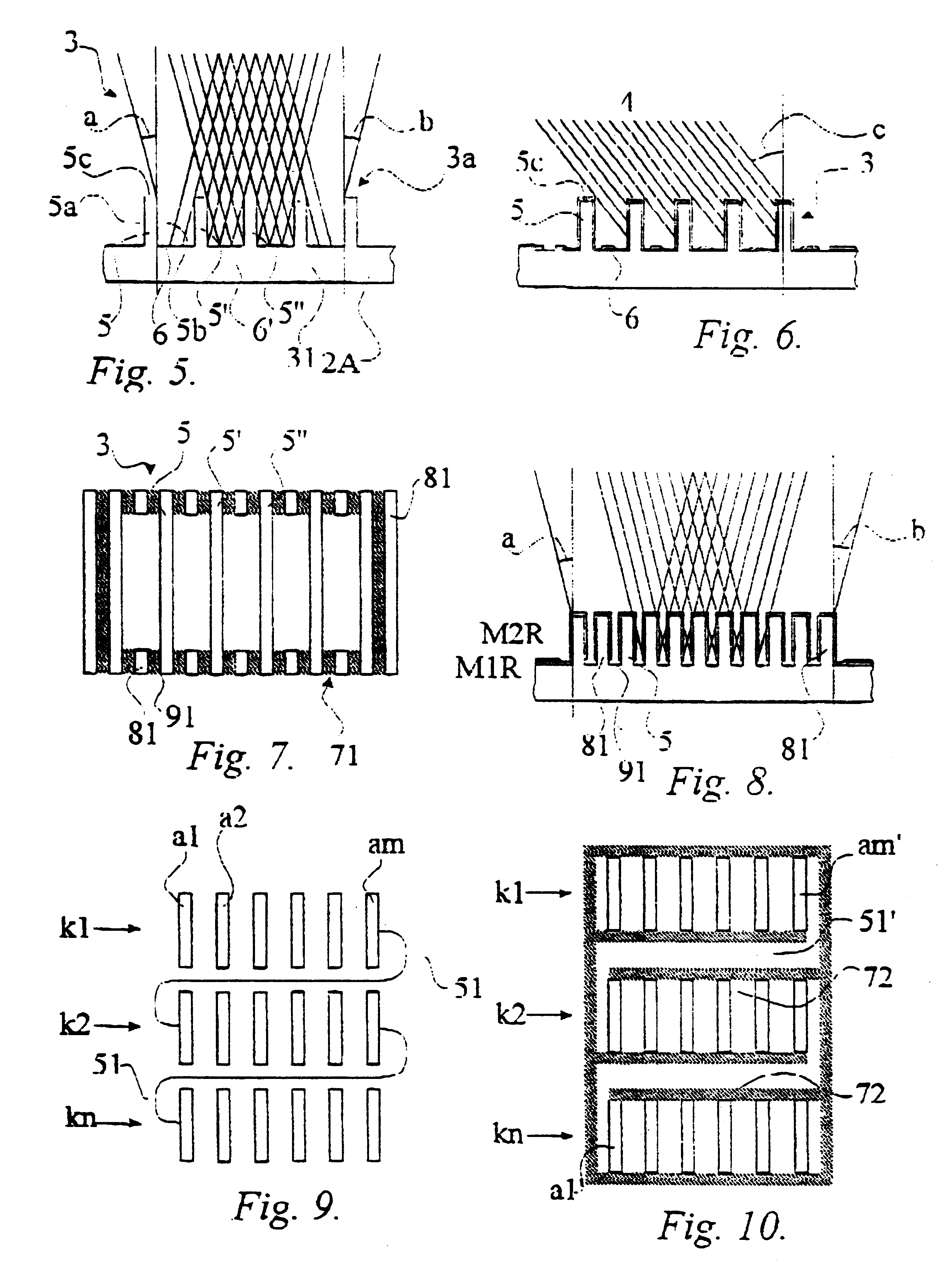
As shown in FIG. 1, a substrate 2 for the thermocouple 1 has a three dimensional structure or configuration 3 and is adapted for further treatment or processing so as to form the end produce, i.e. the thermocouple.

As shown in FIG. 1, the three-dimensional structure 3 for the thermocouple is produced on a delimited surface region, and that electric conductor paths and / or further electric and / or electronic components can be produced on this delimited surface region in mutually the same way.

These further components may comprise an amplifier 1', a voltage unit 1", correction pads, connection terminals 1'", or an electric conductor path 1.sup.4, etc., as shown in...


PUM

PropertyMeasurementUnit
Angleaaaaaaaaaa
Pressureaaaaaaaaaa
Electrical conductivityaaaaaaaaaa

Abstract

The present invention relates to a method of producing an electric, electronic, electromechanical and/or mechanical component (12), where the component substrate is given a three-dimensional structure (3'') or configuration, and where said substrate is adapted for further treatment or processing to form the component (12). The substrate is formed by shaping said substrate against a die or mold, such as by molding, pressing, extruding or embossing said substrate, wherewith the precision necessary with respect to said component in the three-dimensional structure is achieved by means of a micromechanical working process when producing the die or mold.

Description

The present invention relates to a method of producing an electric, electronic, optic and / or mechanical component in which the component substrate is given a three dimensional structure or shape and the substrate then further worked to build the component.DESCRIPTION OF THE BACKGROUND ARTIt has long been known to construct different types of components, such as sensors and mechanical units, with the aid of methods with which the base of the component is formed from silicon, quartz or some other more or less expensive material. In some instances, the material can be worked micromechanically so as to give the material certain three-dimensional forms or structures. These substrates are then processed by adding material to or removing material from certain areas, for instance areas that have been defined with the aid of lithographic techniques.For reasons of a process / technical nature, traditional bases are almost always comprised of a circular disc of substrate material. Subsequent to ...

Claims


Application Information

Patent Timeline
IPC IPC(8): B81C1/00G01N21/31G01N21/35G01J5/12G02B6/36G02B6/42H01L21/48H01L21/02G01N21/03B81B1/00B81C99/00G01N27/447G02B3/00H01L27/16H01L35/08H01L35/34
CPCB81C1/0046G01J5/12G01N21/3504H01L35/34G02B6/3696G02B6/4219H01L21/4803H01L35/08B81B2201/0214B81B2203/0136B81C2201/034G02B6/423G02B6/4246G02B6/3652H10N10/817H10N10/01
Inventor MARTIN, HANS GORAN EVALDOHMAN, PER OVE
Owner CRIMSON INT ASSETS LLC
Why Eureka
Try Eureka