Shape charge assembly system
a charge assembly and shape technology, applied in the direction of explosive charges, blasting cartridges, weapons components, etc., can solve the problems of insufficient infusion of material into the surrounding casing, insufficient sealing, and insufficient performance of conventional perforating guns, and achieve the effect of superior performan
- Summary
- Abstract
- Description
- Claims
- Application Information
AI Technical Summary
Benefits of technology
Problems solved by technology
Method used
Image
Examples
first embodiment
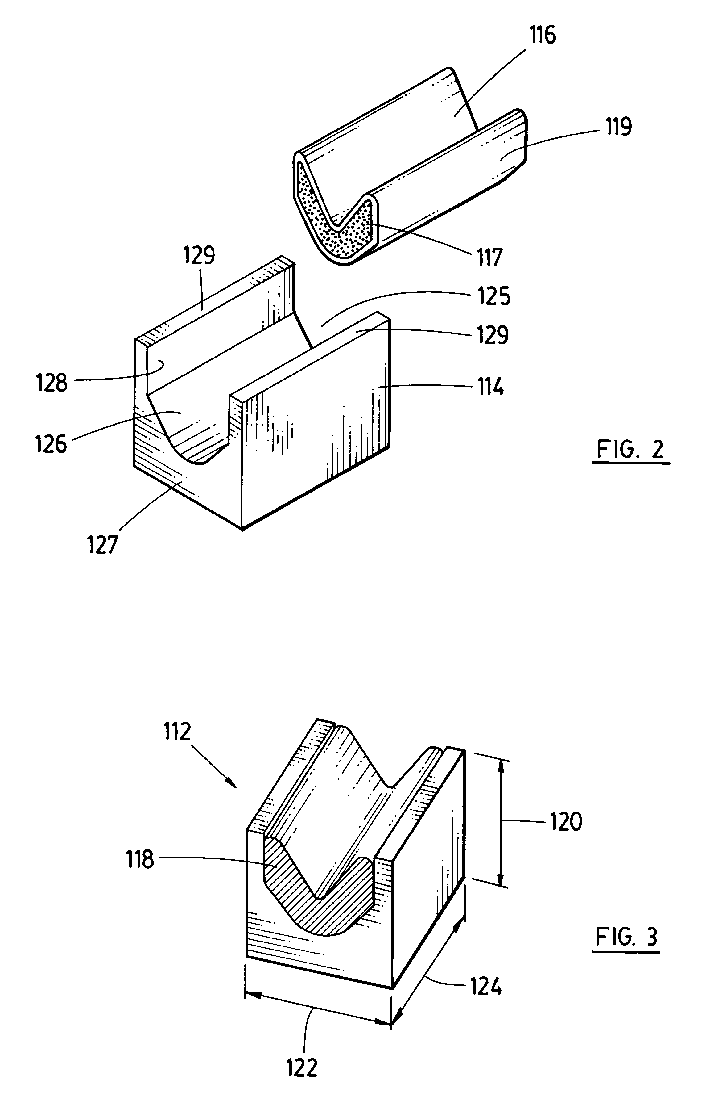
A first embodiment charge assembly 112 is illustrated in greater detail in FIGS. 2 and 3. Device 112 includes rigid base 114 having linear shaped charge 116 (with liner 119) received therein. Charge 116 is a linear shaped charge, cut to the same length as the base 112, the charge containing explosive material 117 compressed within metal sheath 119. Such a linear charge is a continuous core of explosive enclosed in a seamless metal sheath, commercially available from Accurate Arms Company, Inc. of McEewen, Tenn. Exposed ends of the charge are capped with adhesive foil 118 (omitted in FIG. 2).
Charge assembly 112 is appropriately dimensioned to be mounted in a holder so as to fit into a selected gun housing. In the illustrated embodiment, the outer housing of the gun has an outer diameter of 86 mm (33 / 8") and an inner diameter of 68 mm (25 / 8"). Charge holder 14 has an outer diameter of 51 mm (2") and is a tube of thin walled extruded steel, being of substantially constant cross section...
third embodiment
A third embodiment shape charged device 250 is illustrated in FIG. 7, in which the cross sectional shape of the shaped charge 252 is shown. As with other embodiments, base 254 of the assembly might or might not have end walls connecting side walls 256, 258. Interior surfaces of liner 260, the side walls and floor 262 of the base define the shape of the charge, which is compressed within the cavity. The cross sectional width of the cavity defined between the upright parallel inner surfaces 264, 266 of the base is about 30.7 cm (1.2"). The floor of the base has an upraised ridge 268 running between lengthwise ends of the base. The liner has a cross sectional "V"-shape. The depth of the charge increases from line 270 running through the center of the cavity to the peripheral area 272 of the cavity.
fourth embodiment
A fourth embodiment shaped charge assembly 280 is illustrated in FIG. 8. This is similar to the third embodiment assembly, but the cross section of liner 282 is "W"-shaped.
Located within base 214 (or 254) is compacted or compressed explosive material 216. The material is compressed during installation of the liner, in the case of the second embodiment, liner 218. A liner of the present invention is of any metal from which conventional sheaths of linear shaped charges are manufactured: steel, copper, zinc, lead and combinations or alloys of these metals, particularly copper and zinc, or of a suitable powdered metal. A yellow brass liner might be found to be particularly suitable. The liner is installed as part of the assembly by an operation similar to that used in the manufacture of conical charges. The explosive powder is added to the cavity and the base tapped, if necessary, to level the powder. The powder can be preshaped by insertion of an appropriately shaped die into the cavit...
PUM
 Abstract
Description
Claims
Application Information
 - R&D
- Intellectual Property
- Life Sciences
- Materials
- Tech Scout
- Unparalleled Data Quality
- Higher Quality Content
- 60% Fewer Hallucinations
Browse by: Latest US Patents, China's latest patents, Technical Efficacy Thesaurus, Application Domain, Technology Topic, Popular Technical Reports.
© 2025 PatSnap. All rights reserved.Legal|Privacy policy|Modern Slavery Act Transparency Statement|Sitemap|About US| Contact US: help@patsnap.com


