
Dielectric barrier excimer lamp and ultraviolet light beam irradiating apparatus with the lamp

a technology of excimer lamp and excimer lamp, which is applied in the direction of fixed installation, gas-filled discharge tube, lighting and heating apparatus, etc., can solve the problems of poor radiation efficiency of ultraviolet light beam based on power input to excimer lamp 42, low reaching efficiency of excimer lamp,

Inactive Publication Date: 2002-04-30
HOYA SCHOTT
View PDF5 Cites 56 Cited by
  • Summary
  • Abstract
  • Description
  • Claims
  • Application Information

AI Technical Summary

Problems solved by technology

However, the above conventional dielectric barrier excimer lamp unit has the following problems.
However, the reaching efficiency thereof is very low, and most of the above ultraviolet light beam radiated upward comes to nothing.
The radiation efficiency of ultraviolet light beam based on power inputted to the excimer lamp 42 is very poor.
(2) The synthetic quartz used as a material for the above light window 44 is expensive and increases the cost of the unit.
Particularly in a unit in which a plurality of the excimer lamps 42 are provided in the metal container 41 for broadening the irradiation region of the ultraviolet light beam, the light window 44 has a large area, which causes a serious cost problem.
(3) The above light window 44 made of the synthetic quartz causes so-called solarization which is a phenomenon that a color center is generated with slight impurities such as iron and manganese due to irradiation with ultraviolet light beam and blackening takes place. The transmitted-light quantity is attenuated due to the solarization, and as a result, the cleaning effect decreases.
(4) The inert gas such as nitrogen that is flowed into the metal container 41 is effective for decreasing absorption of ultraviolet light beam in the container. On the other hand, it requires an additional cost, and handling thereof requires labors in view of environmental protection.
(5) The outer electrode 42d is exposed on the outer circumference of the excimer lamp 42, so that it is required to take care when the excimer lamp 42 is attached inside the metal container 41. For this reason, the position of the excimer lamp 42 relative to the container is liable to vary when the excimer lamp 42 is attached, and the variability may influence the irradiation performance of the unit.
(6) The above metal container 41 has a relatively large space around the excimer lamp 42 for disposing the above reflection plate and attaching the excimer lamp 42. It is therefore required to constantly flow the inert gas necessary for filling the space with it at a rate of approximately several liters per minute, so that the consumption thereof comes to be very large.
(7) For improving the efficiency of cleaning or modifying the work with ultraviolet light beam, preferably, the distance between the surface of the excimer lamp 42 and the work is shortened so as to make it as small as possible, and the ultraviolet light beam is increased in radiation light quantity. In the conventional lamp unit, however, it is difficult to shorten the above distance due to its structure in which the excimer lamp is housed in the metal container.

Method used


Image

  • Dielectric barrier excimer lamp and ultraviolet light beam irradiating apparatus with the lamp
  • Dielectric barrier excimer lamp and ultraviolet light beam irradiating apparatus with the lamp
  • Dielectric barrier excimer lamp and ultraviolet light beam irradiating apparatus with the lamp

Examples


Embodiment Construction

The dielectric barrier excimer lamp of the present invention includes two embodiments, and the dielectric barrier excimer lamp I will be explained first.

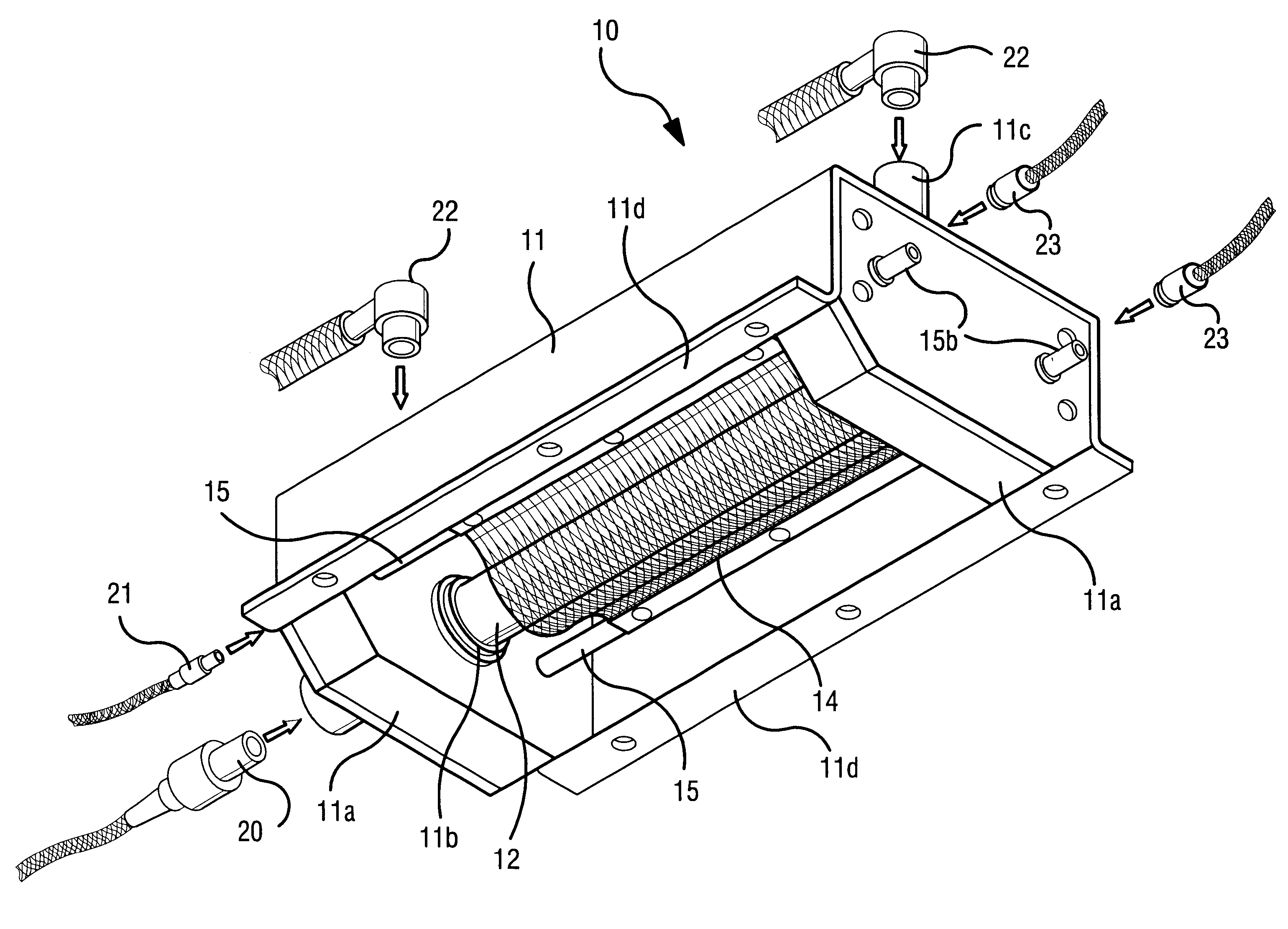
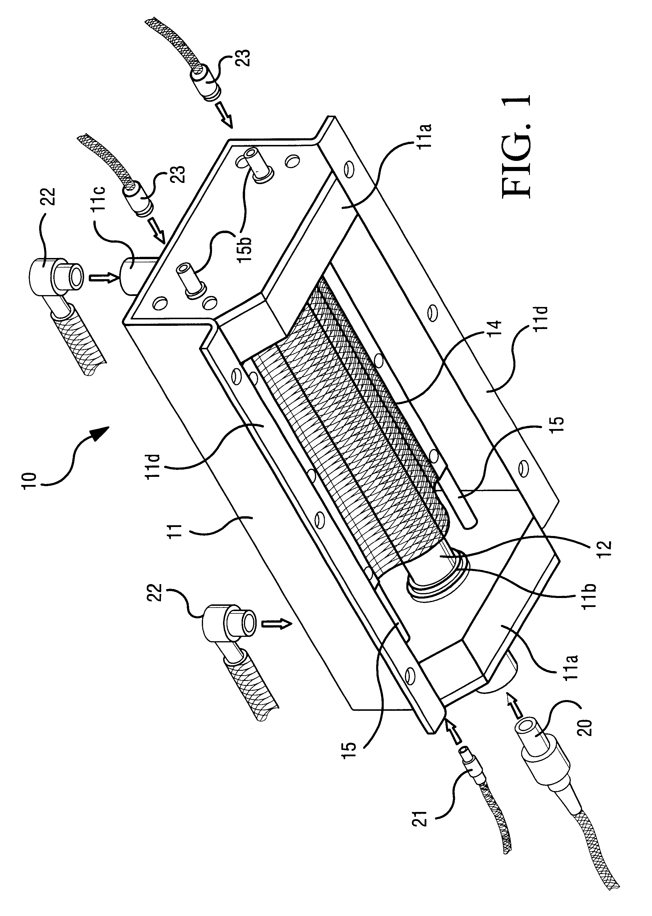
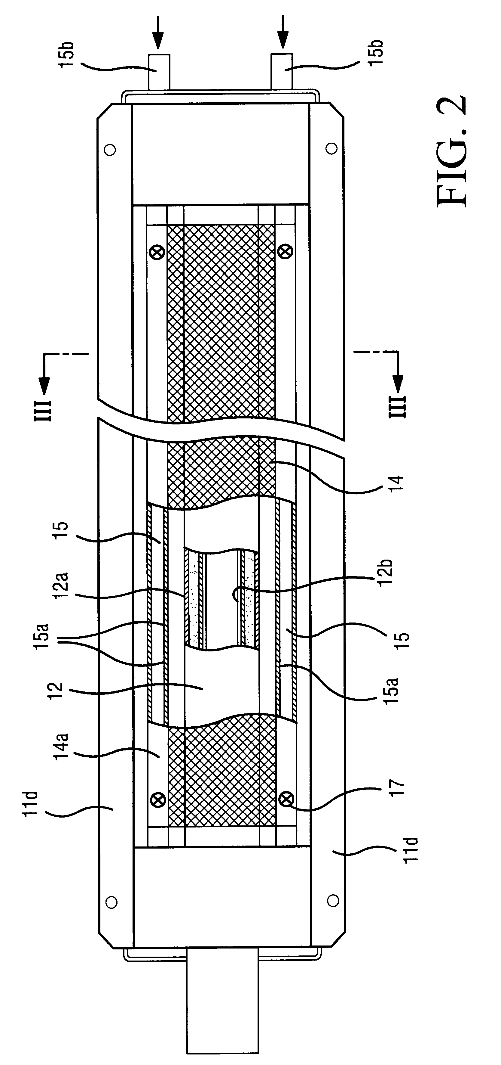
The dielectric barrier excimer lamp I has a dual tube made of a dielectric material, preferably, a quartz glass, the dual tube having an inner tube, a light-transmitting outer tube and an excimer gas, preferably a discharge gas such as xenon gas, sealed in a space between the inner and outer tubes, a case for housing the above dual tube, the case being opened at least on one side in radius direction of said dual tube, an outer electrode which is fixed in an opened region of the above case and includes a network-shaped region disposed close to an external-surface side of the above outer tube in one side of the above dual tube, and an inner electrode disposed on an internal-surface side of the above inner tube which internal-surface side corresponds at least to the region of the surface of the above outer tube which surface is the sur...


PUM


Abstract

Disclosed is a dielectric barrier excimer lamp which is easy to handle, less expensive and improved in ultraviolet light beam irradiation efficiency to electric power and ultraviolet light beam irradiation efficiency to a work.The dielectric barrier excimer lamp comprises a dual tube having an inner tube, an outer tube and a discharge gas sealed in a space between the inner and outer tubes, a case for housing said dual tube, a light-transmitting outer electrode including a network-shaped region disposed on an external-surface side of said outer tube and an inner electrode disposed on an inner-surface side of said inner tube, or comprises a dual tube in which the above discharge gas is sealed, a network-shaped first electrode disposed on the outer circumferential surface of said outer tube, a second electrode disposed in the inner circumferential surface of said inner tube, and a first tube for internally housing said dual tube together with said electrodes inside thereof, an inert gas being introducible into a space between said first tube and said outer tube, wherein a voltage is applied between the electrodes to radiate an ultraviolet light beam.

Description

TECHNICAL BACKGROUND1. Field of the InventionThe present invention relates to a dielectric barrier excimer lamp and an ultraviolet light beam irradiating apparatus to which the dielectric barrier excimer lamp is applied. More specifically, the present invention relates to a dielectric barrier excimer lamp for cleaning or modifying the surface of a semiconductor wafer or a glass substrate by means of joint activities of ultraviolet light beam and ozone, and an ultraviolet light beam irradiating apparatus having the dielectric barrier excimer lamp.2. Related Art StatementIn recent years, studies are being widely made with regard to a method for cleaning or modifying a work such as a metal, a semiconductor substance or a glass by means of the joint activities of ultraviolet light beam and ozone. The above method is generally known as a UV ozone method. The UV ozone method has advantages that an organic contaminant adhering to a work surface can be removed, and that an oxide film can be...

Claims


Application Information

Patent Timeline
IPC IPC(8): H01J61/30H01J65/00H01L21/26H01J61/52H01J65/04
CPCH01J61/30H01J65/046H01J65/00H01J61/52H01L21/26
Inventor KOGURE, YASUOKOBAYASHI, NORIOHIRATSUKA, KATSUMIAMANO, SATORU
Owner HOYA SCHOTT
Learn More