Vibration damping device

a damping device and vibration technology, applied in the direction of fluid couplings, mechanical control devices, instruments, etc., can solve the problems of affecting driving comfort and behavior, affecting the end area of the deflection path, and affecting the damping effect of torsional vibration

Inactive Publication Date: 2002-05-07
ZF FRIEDRICHSHAFEN AG
View PDF20 Cites 54 Cited by
  • Summary
  • Abstract
  • Description
  • Claims
  • Application Information

AI Technical Summary

Benefits of technology

The vibration damping device according to the invention prevents the knocking of a deflection mass and the generation of a vibrational excitation by braking the deflection masses through a gradual slowing down of movement.
In this case, it is advantageous when the stop device is movable in different directions by at least one deflection mass when the at least one deflection mass strikes the different stop areas. Accordingly, the stop device may be moved back and forth alternately by the deflection mass or deflection masses depending on the movement direction.
An embodiment having a simple construction may be achieved when the stop device is elastically deformable at its stop areas. The stop areas may, for example, comprise stop webs proceeding from a main body.
In another embodiment, which may be combined with the possible embodiments discussed above, the braking arrangement may comprise a portion having increased elasticity in the end areas of the deflection areas. In addition, or alternatively, the end areas of the deflection area may comprise a portion with increased rolling or sliding movement resistance. The undesirable colliding of a deflection body in the end areas of its movement may also be prevented by arranging an axially projecting guide pin on the at least one deflection body which moves along at least one guide path during the movement of the at least one deflection body along the deflection path. Furthermore, the guide path is elastically deformable at least in its respective end portions in which the at least one guide pin is located when the at least one deflection mass is positioned in the end areas of the deflection area. Furthermore, the associated guide pin may also be elastically deformable.
As discussed above, the problem of the prior art in which the deflection masses collide at structural component groups terminating the movement path of the deflection masses occurs when there is a relatively strong vibrational excitation which leads to correspondingly large deflections. Accordingly, a further possibility provided by the present invention for improving the damping behavior by preventing a collision at path ends is directed toward enlarging the movement area of the individual deflection masses while retaining the same constructional volume. Therefore, a further embodiment of the present invention includes a vibration damping device for a drive system of a motor vehicle comprising a deflection mass arrangement arranged in a base body which is rotatable about an axis of rotation. The deflection mass arrangement has at least two deflection masses and a deflection path which is associated with each of the deflection masses and along which the deflection masses can move during rotation of the base body about the axis of rotation. The deflection path has a vertex area and deflection areas on both sides of the vertex area. The deflection areas have end areas and are arranged so that a distance of the deflection area from the axis of rotation decreases as the deflection area proceeds from the vertex area toward the end areas. The at least two deflection paths adjoin one another in respective adjacent end areas and an overlapping volume is formed in the area of the adjoining end. Each of the deflection masses associated with the two adjoining deflection paths projects into the overlapping volume when it is positioned in the respective end area of the deflection path associated with it.
The above arrangement ensures that there is a volume area in which different deflection masses may engage depending on the vibrational deflection. However, since each of the deflection masses move in phase, i.e., in the same circumferential direction, the state in which both deflection masses of directly adjacent deflection paths attempt to enter simultaneously into the overlapping volume area does not occur. Accordingly, the available volume may be used in an overlapping manner by a plurality of deflection masses, thereby allowing the movement paths to be lengthened. The increased length of the movement path may be used to reduce the risk of striking against end areas of the deflection path or increase the quantity of oscillating masses.

Problems solved by technology

This movement of the deflection masses damps torsional vibrations, especially periodic torsional vibrations.
Since the deflection paths have only a limited circumferential extension, the deflection masses may knock against the end areas of the deflection paths when deflection amplitudes are too great.
This impairs driving comfort as well as the behavior for minimizing vibrational excitations generated in an existing drive system.
Moreover, the movement may occur against the action of a restoring spring arrangement.
As discussed above, the problem of the prior art in which the deflection masses collide at structural component groups terminating the movement path of the deflection masses occurs when there is a relatively strong vibrational excitation which leads to correspondingly large deflections.

Method used


Image

  • Vibration damping device
  • Vibration damping device
  • Vibration damping device

Examples


Embodiment Construction

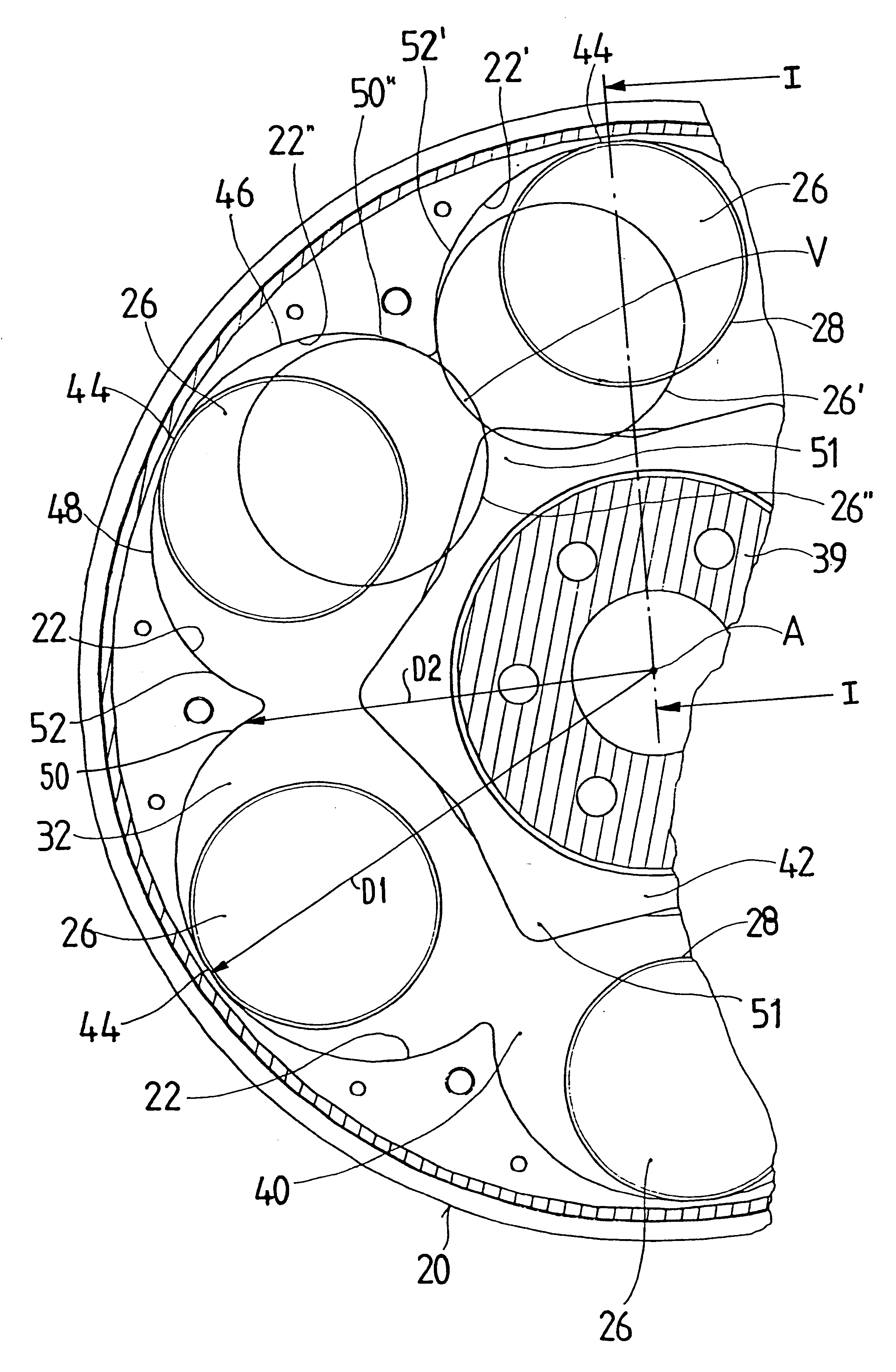
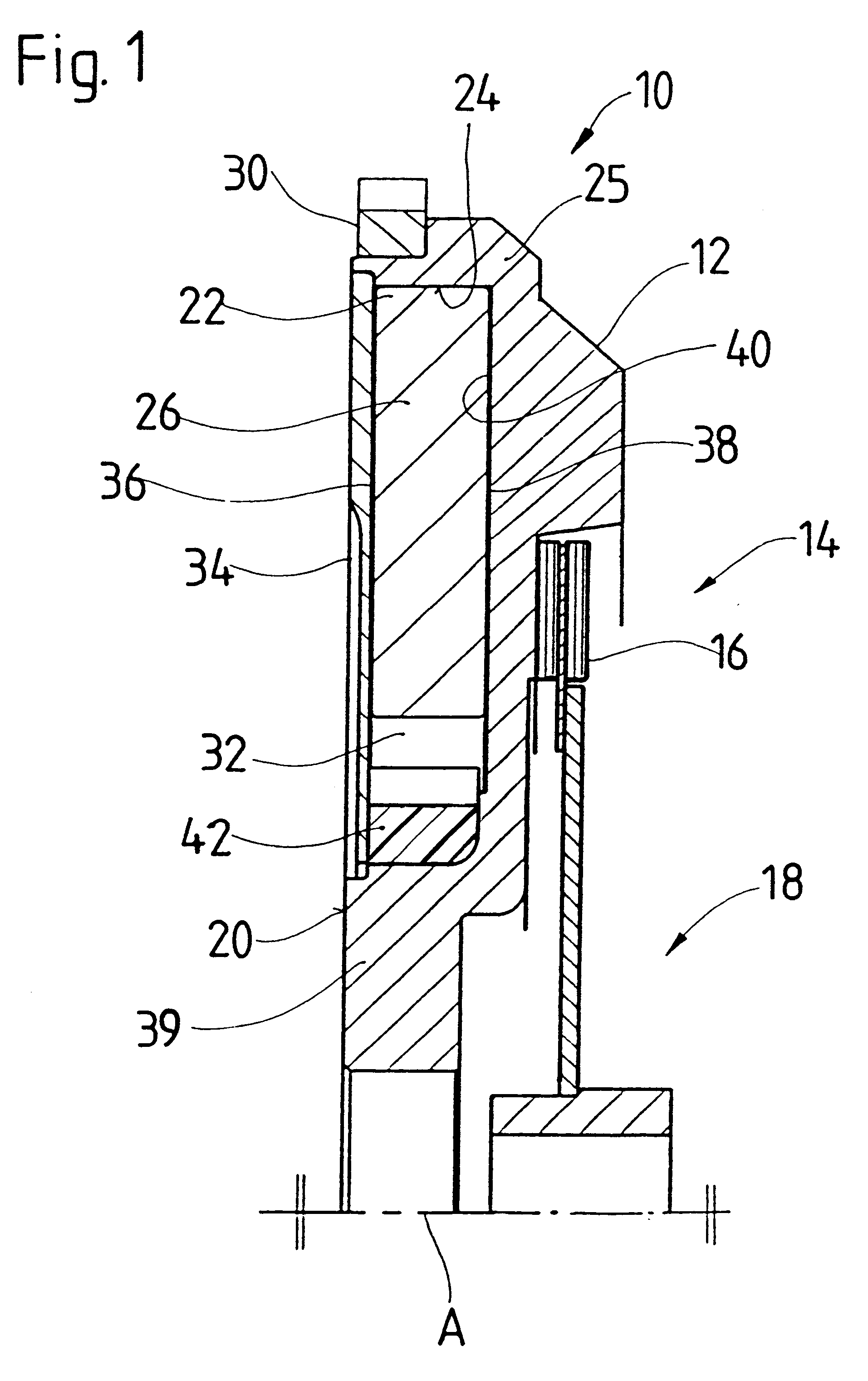
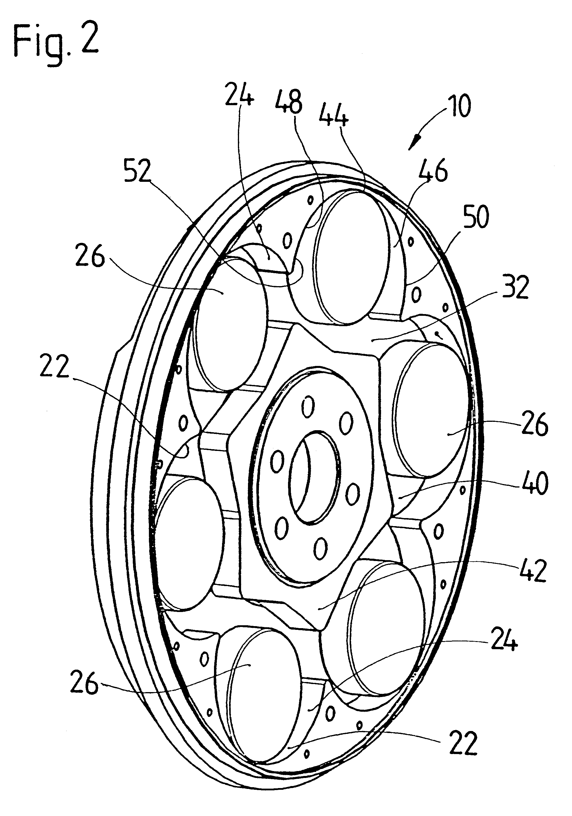
A vibration damper 10 according to an embodiment of the present invention is shown in FIGS. 1 to 3. The vibration damper 10 is provided for use with a flywheel 12 of a motor vehicle clutch 14 which is indicated only schematically. This flywheel 12 is engagable with friction facings 16 of a clutch disk 18 so that a driving force is conducted via a drivetrain from a driving unit coupled with the flywheel 12 to driving wheels when the clutch 14 is engaged. It is noted that the vibration damper 10 as shown here in connection with the flywheel 12 at a drivetrain of a vehicle, may also be used in a wide variety of other rotating systems or may be used in other spatial areas of such a flywheel or clutch arrangement. For example, the vibration damper may also be positioned in the clutch housing or in a pressure plate of a clutch.

The flywheel 12 forms a base body 20 for the vibration damper 10. As shown in FIGS. 2 and 3, a depression 32 is arranged in the base body 20. The radial outer side ...


PUM


Abstract

A vibration damping device for a drive system of a motor vehicle includes a base body arranged for rotating about an axis of rotation and a deflection mass arrangement arranged in said base body and having at least one deflection mass and a deflection path associated with the at least one deflection mass and along which the deflection mass is movable during rotation of the base body about the axis of rotation. The deflection path has a vertex area at a position furthest from the axis of rotation and deflection areas on both sides of the vertex area extending from the vertex area to ends areas. The deflection areas have a decreasing distance from the axis of rotation (A) proceeding from the vertex area toward their end areas. A braking arrangement acts in the end areas of the deflection areas for gradually slowing the approach of the at least one deflection mass to a respective end area of the deflection path.

Description

1. Field of the InventionThe present invention is directed to a vibration damping device including a base body rotatable about an axis of rotation and a deflection mass arrangement arranged in the base body, the deflection mass arrangement having at least one deflection mass and a deflection path associated with the at least one deflection mass and along which the deflection mass is movable during rotation of the base body about the axis of rotation, wherein the deflection path has a vertex area and deflection areas on both sides of the vertex area the deflection areas have a decreasing distance from the axis of rotation proceeding from the vertex area toward their end areas.2. Description of the Related ArtA vibration damping device is disclosed in DE 44 26 317 A1 having a base body with a deflection mass arrangement including deflection masses arranged in deflection paths having vertex areas and deflection area. This reference further discloses disklike deflection masses distribut...

Claims


Application Information

Patent Timeline
Patent Type & Authority Patents(United States)
IPC IPC(8): F16F15/10F16F15/14F16F15/30F16F15/31
CPCF16F15/145Y10T74/2111
Inventor CARLSON, CORAPEINEMANN, BERNDWETH, JURGEN
Owner ZF FRIEDRICHSHAFEN AG
Why Eureka
Try Eureka