Ultrasound transducer

a transducer and ultrasound technology, applied in the field of ultrasound transducers, can solve the problems of reducing the quality of ultrasound images to be produced, causing the degradation of the directional resolution, and the delay in signal reception time in the peripheral portions of the active surfa

Inactive Publication Date: 2002-05-07
FUJI PHOTO OPTICAL CO LTD
View PDF3 Cites 18 Cited by
  • Summary
  • Abstract
  • Description
  • Claims
  • Application Information

AI Technical Summary

Problems solved by technology

Generally, an ultrasound beam which is transmitted from a transducer element tends to spread or diverge in the travel direction, and, particularly in case of a transducer with a broad active surface, this tendency becomes very conspicuous to invite degradations in directional resolution.
Besides, in receiving return echoes from various tomographic scan areas of different acoustic impedances, delays in signal reception time occurs in peripheral portions of the active surface as compared with center portions thereof.
These delays in reception time phase result in degradations in picture quality and sharpness of ultrasound images to be produced.
Nevertheless, acoustic lenses are normally fixed in focal distance and therefore incapable of focusing to a position which is at a desired depth or of shifting a focus position over a certain range in depth in the manner as in the so-called dynamic focusing.
The ceramic semiconductor materials as just mentioned have a drawback that it is difficult to fabricate the transducer elements into a desired shape.
However, it is necessary to form transducer elements into annular or arcuate shapes especially in case they are to be arranged in an annular array, despite the difficulties which are encountered in machining the ceramic semiconductor material precisely to predetermined surface curvatures.
Due to high probabilities of fractures and cracking in a fabrication process, transducer elements of this sort are usually very expensive.
Nevertheless, as compared with the ceramic semiconductor type transducer elements, generally transducer elements of a high polymer type piezoelectric material are inferior in transmission efficiency and mechanical strength.
The polygonal array approaches a circle in shape if the number of apexes is increased from tetragon to hexagon, from hexagon to octagon and so forth, but an increased number of apexes will make it more complicate to fabricate and assemble the transducer elements of the respective frame units.

Method used


Image

  • Ultrasound transducer
  • Ultrasound transducer
  • Ultrasound transducer

Examples


Embodiment Construction

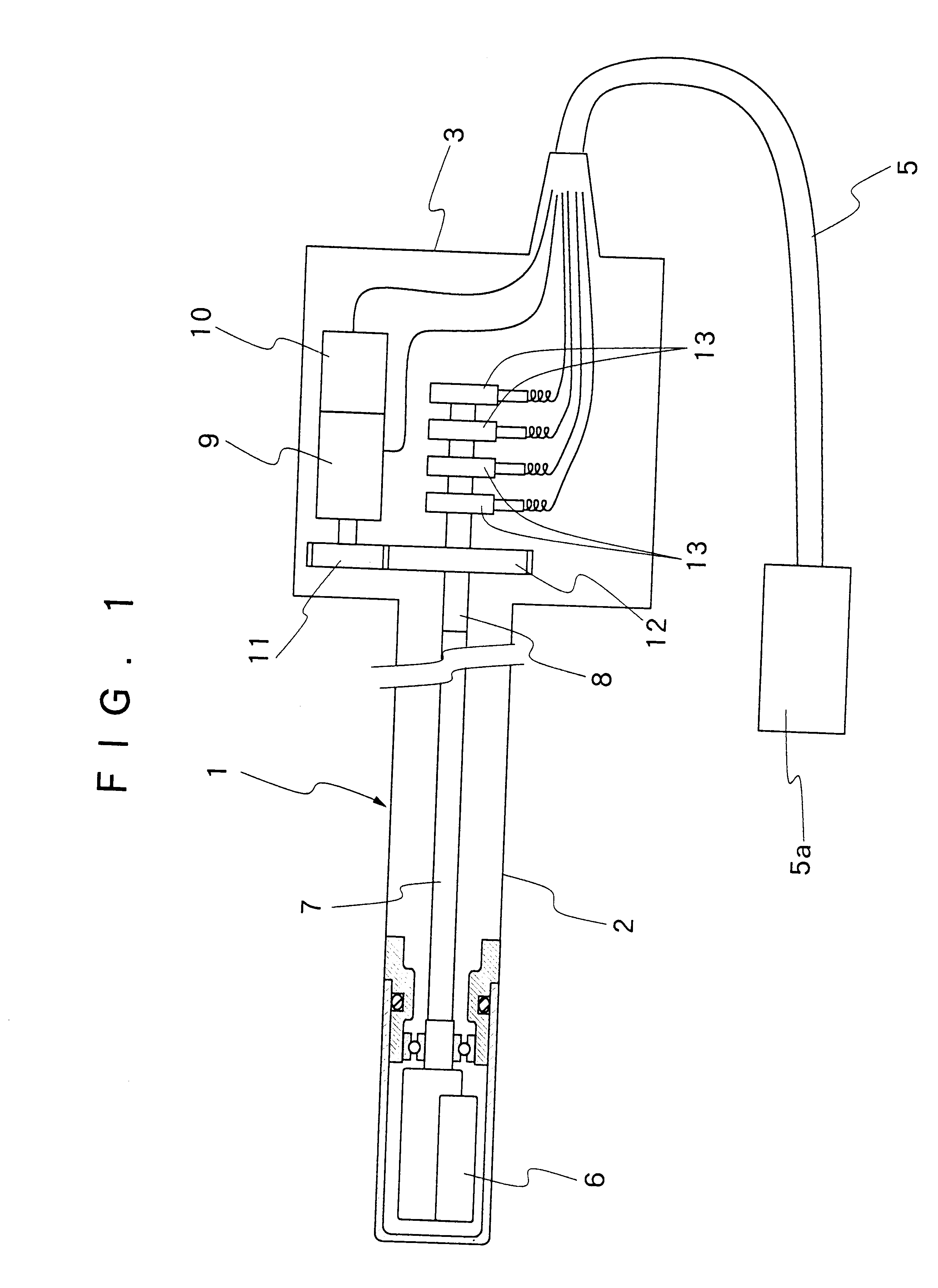
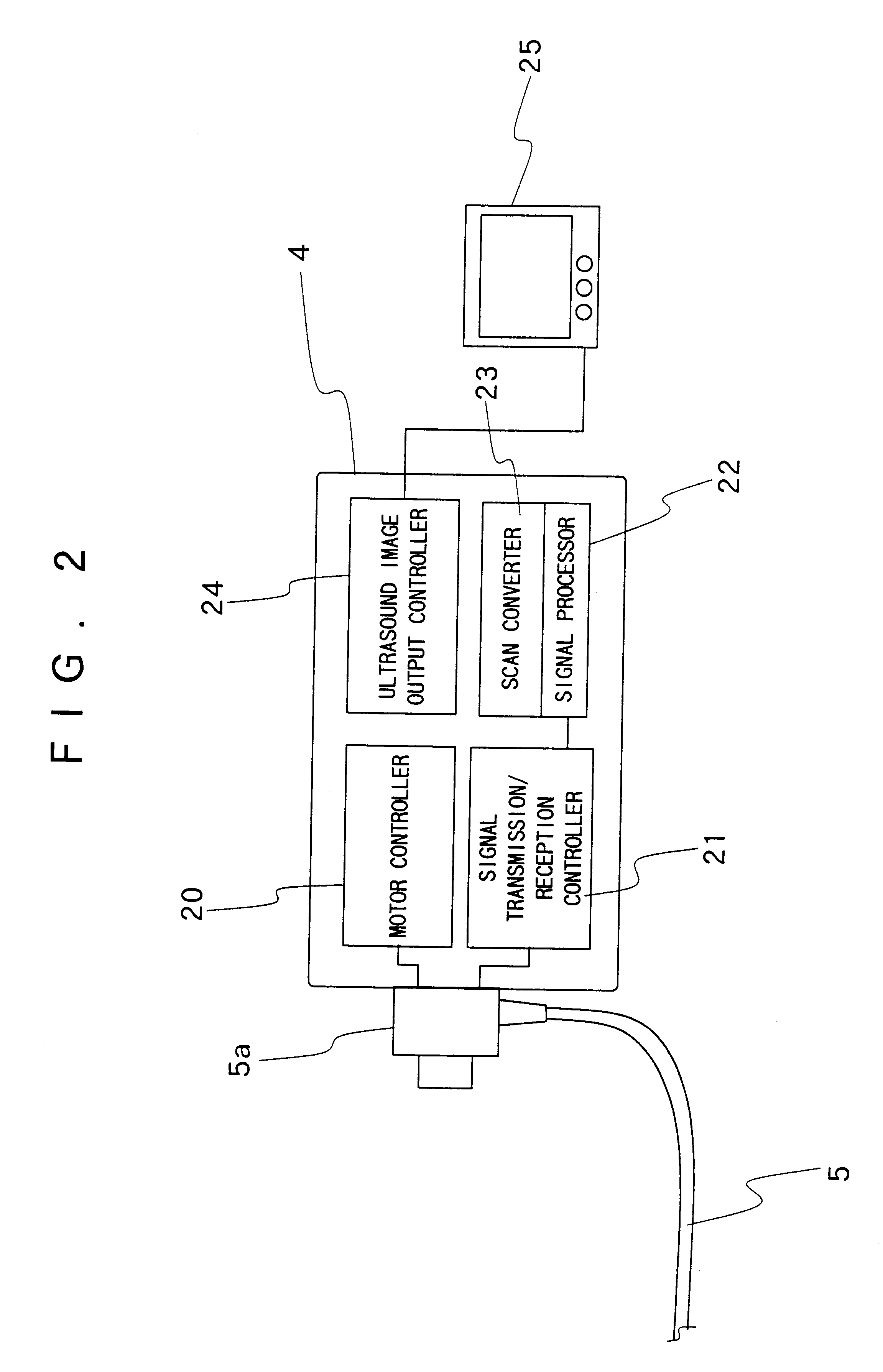
Hereafter, the present invention is described more particularly by way of its preferred embodiments with reference to the accompanying drawings. Schematically shown in FIG. 1 is the general layout of an ultrasound examination system having an ultrasound probe 1. The ultrasound probe 1 is provided with a manipulating control head 3 at a proximal end of an insert portion 2 to be introduced into a body cavity of a subject. Connected to the manipulating control head 3 is a cable 5 which is provided with a connector 5a at its proximal end to be disconnectibly connected to an ultrasound image processing and observing terminal 4 (FIG. 2).

Accommodated within a cap 2a, which is provided at the fore distal end of the insert portion 2, is an ultrasound transducer 6 to scan body tissues of a subject from an intracavitary site of interest. This ultrasound transducer 6 is of a radial scan type and therefore rotatable within the cap 2a. In addition to radial scans, for example, it is possible to m...


PUM


Abstract

An ultrasound transducer having transducer elements arrayed in a polygonal shape on a common plane. The polygonal array of transducer elements includes a core unit consisting of a single transducer element of a polygonal shape and a plural number of frame units each consisting of a plural number of transducer elements arranged in a polygonal shape around the transducer element of the core unit. Each one of the transducer elements of the frame units are formed in the shape of a square block and electrically connected to adjacent transducer elements of the same frame unit but insulated from transducer elements of an adjacent frame unit through an insulating coat layer.

Description

1. Field of the ArtThis invention relates to an ultrasound transducer with an electronic focusing function.2. Prior ArtMedical ultrasound examination systems are used mainly for acquiring information on conditions of patient's body tissues or the like. Ultrasound examination systems are equipped with an ultrasound probe including an ultrasound transducer consisting of a piezoelectric transducer element or elements. The transducer element of this sort functions to transmit an ultrasound beam into a patient's body and to receive echo signals from body tissues in various portions of a tomographic area or in positions of different acoustic impedances. The received return echo signals received by the transducer element are converted into electric signals, which are then transferred to an ultrasound sound signal processor to undergo various signal processing operations and thereby converted into video signals to be displayed on a viewing screen as ultrasound images. An ultrasound image is...

Claims


Application Information

Patent Timeline
Patent Type & Authority Patents(United States)
IPC IPC(8): A61B8/12B06B1/06G10K11/34G10K11/00B06B1/02H04R17/00
CPCA61B8/12A61B8/4483G10K11/346B06B1/0607B06B1/0622A61B8/4488A61B8/4461B06B2201/76A61B8/4494
Inventor ITOI, HIROMU
Owner FUJI PHOTO OPTICAL CO LTD
Why Eureka
Try Eureka