
Profile clamp and method for manufacturing a profile clamp

a technology of profile clamps and profiles, applied in the field of profile clamps, can solve the problems of low production efficiency, low stability of steel profile clamps at relatively high temperatures, and loss of elasticity at high temperatures

Inactive Publication Date: 2002-05-07
ABB (SCHWEIZ) AG
View PDF21 Cites 20 Cited by
  • Summary
  • Abstract
  • Description
  • Claims
  • Application Information

AI Technical Summary

Benefits of technology

Martensitic steel has a high degree of hardness at very high temperatures and, therefore, withstands high forces that are exerted on the point of junction without being deformed. Furthermore, as a result of the selection of the coefficient of thermal expansion, the profile clamp expands slightly less than the components that are being joined, which are made of a ferritic casting material. The clamping force exerted by the profile clamp on the flanges of the components to be joined increases as the temperature of the joint rises, thereby ensuring that the components will be held together not only due to the lower deformability of the profile clamp, but also because the clamping force increases with rising temperature. Thus, in use, the profile clamp according to the present invention not only avoids the dangers described above, but also avoids the costly manner that is currently used to bolt known profile clamps, which may include the use of additional clamping rings that are fitted with holes for the insertion of screws to further secure the joint.
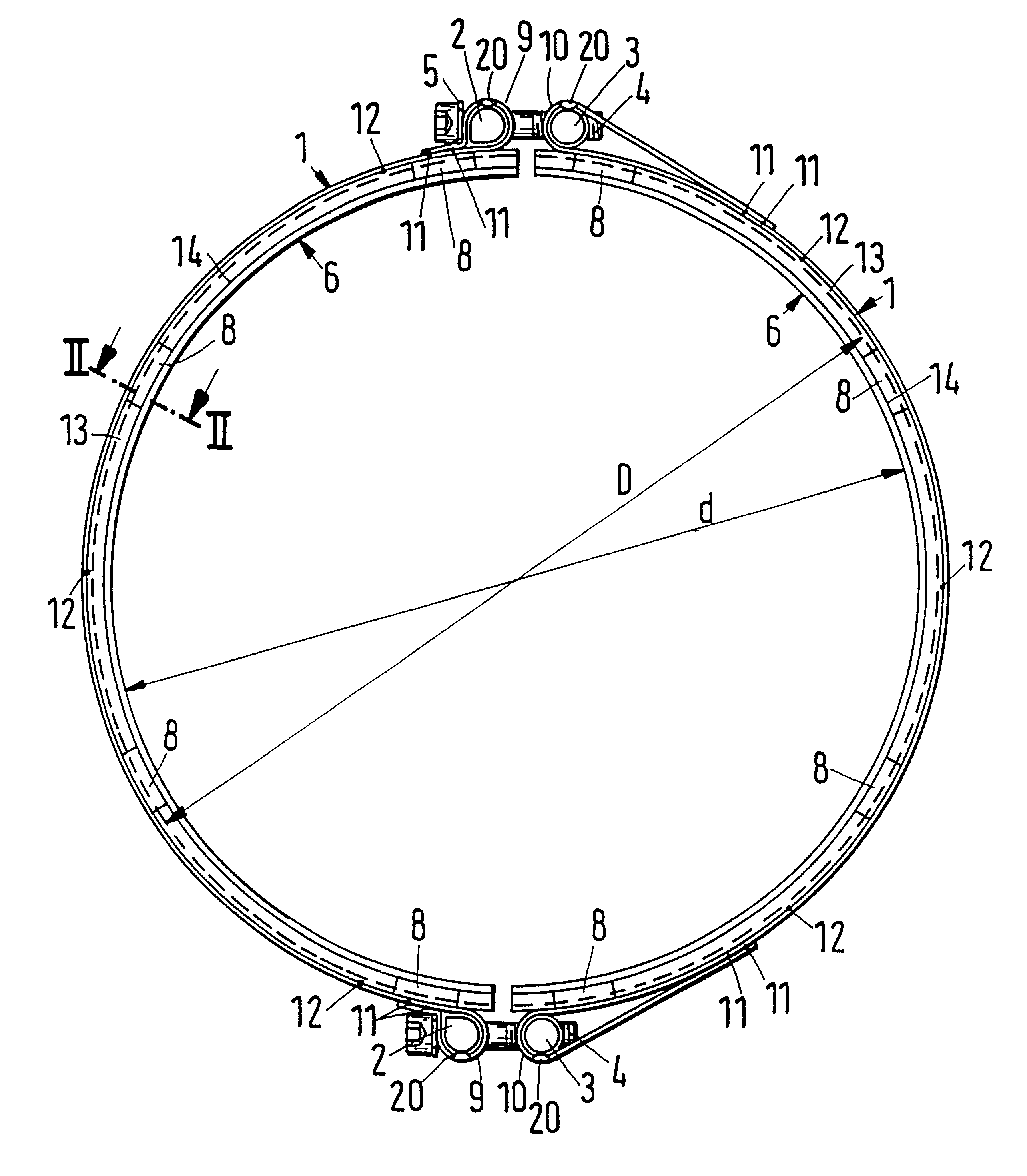
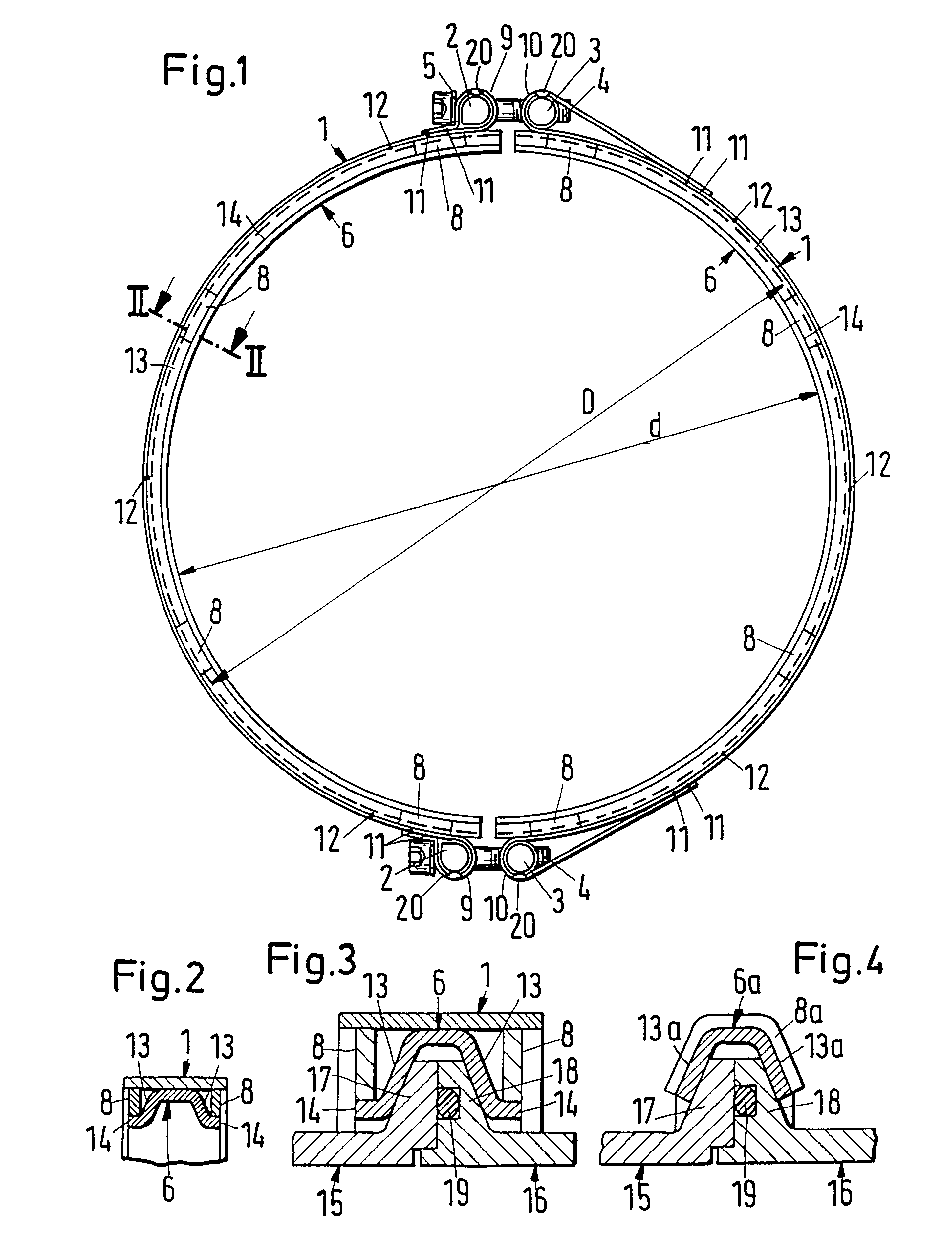
The profile clamp in one exemplary embodiment of the present invention has at least one clamping band with its end sections being bent radially outwardly and back to form loops. The ends of the end sections are welded to the clamping band. A bolt is disposed in each loop. Each loop has a slit that extends around a major portion of the bolt. The bolts in adjacent loops are connected by a headed clamping bolt. The clamping bolt shaft extends through the slits in the loops. At least one circular ring segment is welded to a radial inner surface of the clamping band. The circular ring segment has conical side walls so that, in axial cross-section, the ring segment is approximately hat-shaped. The conical side walls are fitted with a plurality of reinforcements. One of the bolts disposed within the loops has, in axial cross-section, an approximately tear drop shape with its sides enclosing a right angle. One of the sides of the tear drop shaped bolt extends radially outwardly away from the clamp circumference and the other side extends approximately in the circumferential direction of the clamp. The loop enveloping the tear drop shaped bolt has a matching cross sectional shape. The clamping bolt head is supported on the side of this matching loop that extends radially outwardly and away from the clamp circumference. The profile clamp according to this embodiment withstands, on the basis of its shape alone, very high axial forces, such as may occur in profile clamps with diameters of up to 500 mm and higher. Nevertheless, the clamping band is sufficiently flexible to adapt perfectly to the diameter of the flanges of the components to be joined together because of the separate construction of the semi-circular profiled ring segments and their connection to the clamping band in a circumferential direction. Because the clamping bolt head is supported on the side of the loop, the width of the slit formed in this loop is smaller than in known profile clamps where the clamping bolt head is supported directly on the bolt disposed within the loop. Thus, the clamp according to the present invention has a slit width in the loop that is approximately equal to the diameter of the clamping bolt shaft so that the loop can withstand higher tension forces. Additionally, the clamping bolt head is supported on a large surface on an approximately radially extending side of the loop, without putting stress on the loop with the edge of the clamping bolt head.
A plain washer, having a diameter larger than that of the head of the headed clamping bolt, is disposed between the head of the headed clamping bolt and the loop. Such a plain washer facilitates not only the tightening of the clamp bolt, but also reduces the surface pressure between the clamping bolt head and the side of the loop.
The method for manufacturing the profile clamp according to the present invention includes the material being prequenched and tempered while in the form of a strip. Thereafter, the clamping band is shaped and welded. The welds are subject to an induction tempering treatment for structural homogenization of the profile clamp. By prequenching and tempering, optimal technological properties are obtained in the steel. The induction tempering, which preferably occurs after controlled cooling of the welds, avoids or at least reduces the risk of crack formation in the area of the welds.

Problems solved by technology

These steel profile clamps are not stable at relatively high temperatures.
Alternatively, they have too high of a coefficient of thermal expansion [18.times.10.sup.-6 to 22.times.10.sup.-6 m / m.degree. C. (for austenitic, creep-resistant steels)], which causes loss of elasticity at high temperatures and, thus, leakages in the joint.
Thus, the known profile clamps, which are made of ferritic or pure austenitic steel, are not suited to join the housing or other components of turbo chargers because the joint would leak at temperatures up to 750.degree. due to the excessively high coefficients of thermal expansion of the conventional clamp material.
Leaking joints will, among other things, lead to a substantial loss of output from the turbochargers.
In addition, a leaking or loosening connection constitutes a security risk, because turbochargers that have been assembled with these clamps could burst as a result of the loose connection, thereby increasing the risk of injury.

Method used


Image

  • Profile clamp and method for manufacturing a profile clamp
  • Profile clamp and method for manufacturing a profile clamp

Examples


Embodiment Construction

Referring now to FIGS. 1-3, a profile clamp according to the present invention is illustrated. The profile clamp includes two approximately semicircular clamping bands 1, four bolts 2, 3, two clamping bolts 4, two plain washers 5, two approximately semicircular ring segments 6 and a plurality of reinforcements, which are preferably in the form of sheet metal strips 8. Sheet metal strips 8 are distributed over the circumference of the clamp on both sides of the circular ring segments 6. Each clamping band 1 has end sections that are bent radially outwardly and back to form loops 9. The ends of the clamping band 1 are welded by, for example, projection welds 11, to the clamping band 1 to maintain the shape of the loops 9, 10. One bolt 2, 3 is placed within each loop 9, 10. Each loop 9, 10 has a slit extending around a major portion of the respective bolts 2, 3. One of the headed clamping bolts 4 has its shaft extend through the slits within the loops 9, 10. The shaft of bolt 4 also ex...


PUM

PropertyMeasurementUnit
Temperatureaaaaaaaaaa
Lengthaaaaaaaaaa

Abstract

A steel profile clamp is used to join flanged component parts. The profile clamp has at least partially conical side walls that are bent radially inwardly. The profile clamp has welding joints to maintain the shape of the clamp. The steel is martensitic for increased load-carrying capacity of the joint. The steel material, in an ambient temperature range of 20° C. to 750° C., has a coefficient of thermal expansion that is at least 0.3x10⁻⁶ m / m° C. lower than that of the coefficient of thermal expansion of a ferritic casting material. The method for manufacturing the profile clamp includes prequenching and tempering the material of the profile clamp when it is in the form of a strip. After forming and welding the profile clamp, the weld is subject to induction tempering.

Description

1. Field of the InventionThe present invention relates to a profile clamp and a method for manufacturing the profile clamp. More specifically, the present invention relates to a profile clamp, having conical side walls that are bent radially inwardly, for connecting components that have flanges at their respective ends.2. Discussion of the Related ArtProfile clamps, per se, are known, for example, from German Reference DE 30 38 491 C2, U.S. Pat. Nos. 3,498,649, 3,964,773, French Reference No. 1,016,629 and from the brochures "NORMA Conical Flange Joints", .COPYRGT. 1979 and 1988, "NORMA Profile Clamp with Conical Flange",.COPYRGT. November 1996. These known profile clamps are made of ferritic or pure austenitic steel. They are manufactured by pure cold forming, with subsequent welding. These steel profile clamps are not stable at relatively high temperatures. Alternatively, they have too high of a coefficient of thermal expansion [18.times.10.sup.-6 to 22.times.10.sup.-6 m / m.degree....

Claims


Application Information

Patent Timeline
IPC IPC(8): C22C38/44F16L23/00F16L23/10F16L23/08C22C38/00F16L23/04C22C38/58F16B2/08F16L23/02F16L33/04
CPCC22C38/44F16L23/10F16L23/08F01N13/1805F16L33/12B23P15/00
Inventor KREIPE, HANS-JURGENWEISHEIT, CLAUS DIETER
Owner ABB (SCHWEIZ) AG
Learn More