Electrostatic microactuator with offset and/or inclined comb drive fingers

a comb drive finger and micro-actuator technology, applied in the field of electrostatic actuators, can solve the problems of limited maximum motion of electrostatic comb drive micro-actuators and side instability, and achieve the effects of minimizing sidewise movement or snapover, enhancing alignment and minimizing nonlinear travel of comb drive fingers during deflection

Inactive Publication Date: 2002-05-07
COHERENT INC
View PDF5 Cites 46 Cited by
  • Summary
  • Abstract
  • Description
  • Claims
  • Application Information

AI Technical Summary

Benefits of technology

Several notable solutions for minimizing sidewise movement or snapover of comb drive fingers in linear electrostatic microactuators are set forth in U.S. Pat. No. 5,998,906. The linear comb drive assemblies described in the '906 Patent are disposed between first and second folded-beam suspensions, which enhance alignment of the comb drive fingers during deflection and thus minimize nonlinear travel of the comb drive fingers during deflection. Each of the folded-beam suspensions therein consists of a pair of beams connected in series. The pair of beams of each folded-beam suspension are connected at one end to a common bar. The opposite ends of such beams are connected either to a movable shuttle or to the fixed substrate. The compliance of a folded-beam suspension in the sideways direction results from two effects caused by the side load, namely individual beam extension o...

Problems solved by technology

The maximum motion of electrostatic comb drive microactuators is often limited by electromechanical side instability forces which occur during interdigitation.
In this regard, undesirable sidewise movement and possible snapover of the comb drive fingers can result f...

Method used


Image

  • Electrostatic microactuator with offset and/or inclined comb drive fingers
  • Electrostatic microactuator with offset and/or inclined comb drive fingers
  • Electrostatic microactuator with offset and/or inclined comb drive fingers

Examples


Embodiment Construction

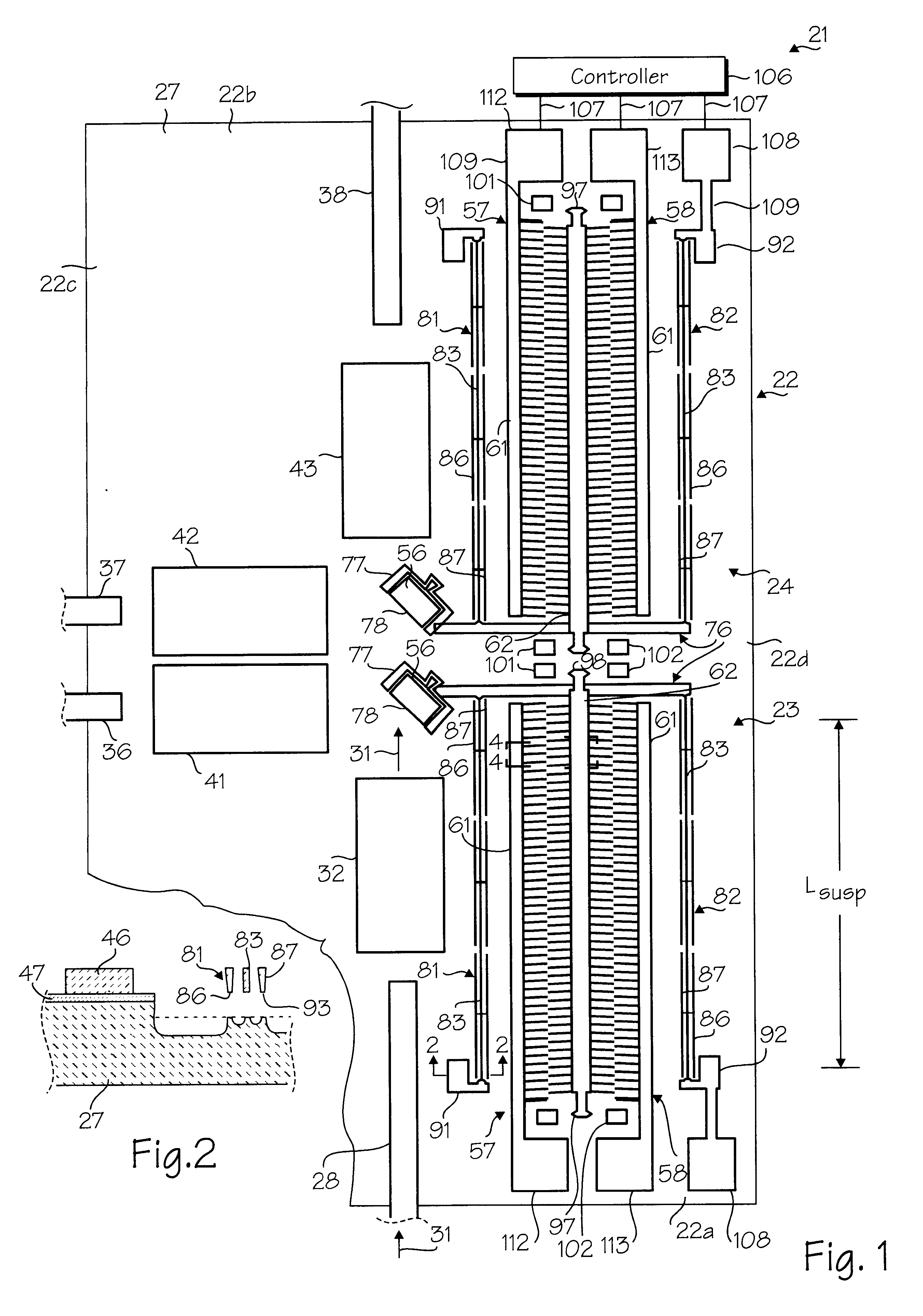
The electrostatic microactuators of the present invention can be used in a variety of devices such as an optical microswitch. Exemplary optical microswitch 21 shown in FIG. 1 is a substantially planar device formed from a microchip 22 of any suitable size and shape. Miicrochip 22, shown in plan in FIG. 1, is rectangular in shape and has first and second opposite ends 22a and 22b and first and second opposite sides 22c and 22d. The microchip 22 has a length ranging from 1000 to 5000 microns and preferably approximately 2500 microns and a width ranging from 1000 to 5000 microns and preferably approximately 2000 microns. The microchip is formed from a base or substrate 27 made from any suitable material such as a silicon wafer.

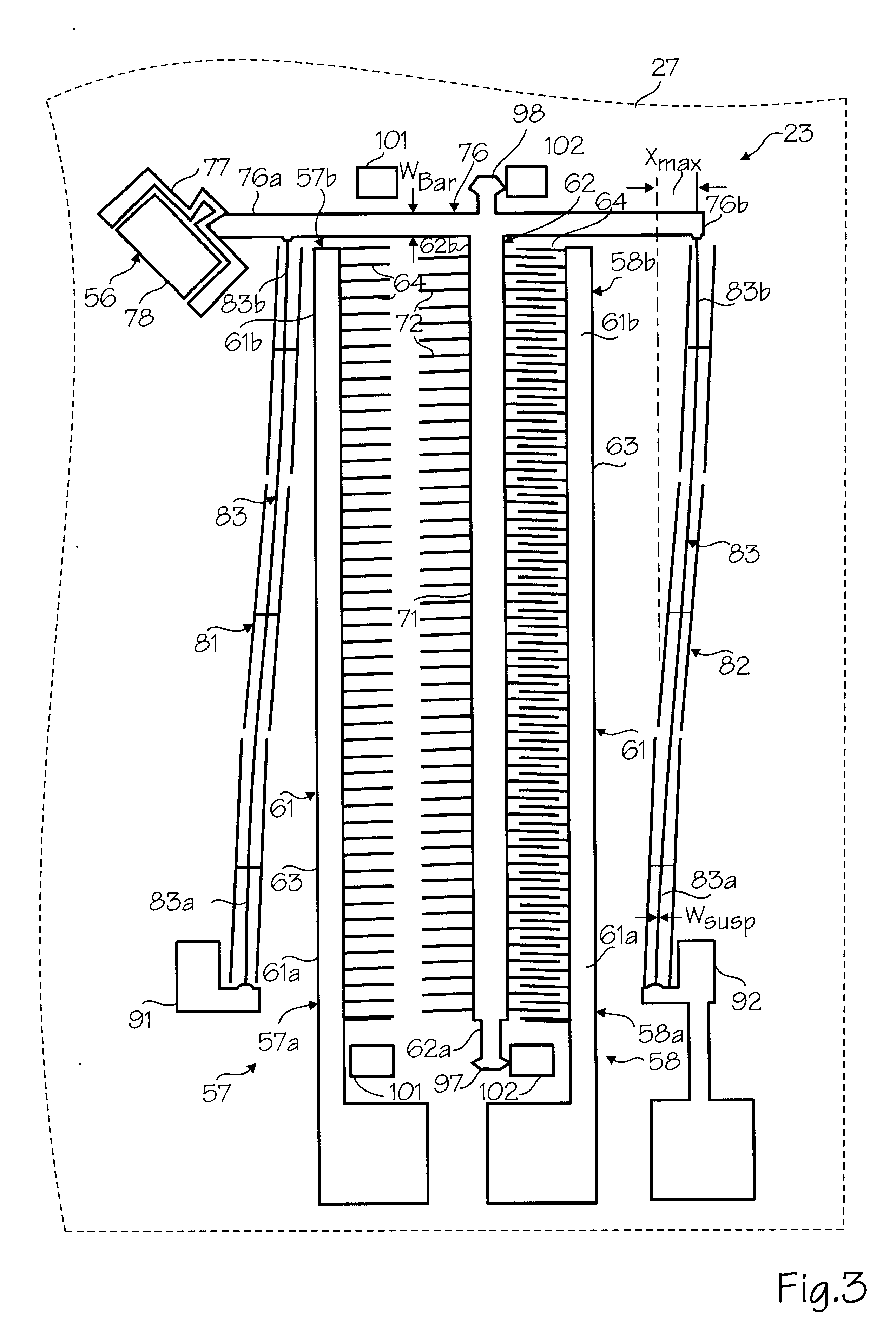
At least one and as shown a plurality of two electrostatic microactuators in the form of first and second linear micromotors 23 and 24 are included in the optical microswitch 21 (see FIG. 1). At least one input optical fiber 28 is optionally provided for carrying...


PUM


Abstract

An electrostatic microactuator comprising a substrate and at least one comb drive assembly having a first comb member mounted on the substrate and a second comb member overlying the substrate. The first comb member has a plurality of first comb fingers. The second comb member has a plurality of second comb fingers. The second comb member is movable between a first position in which each second comb finger is not substantially fully interdigitated with an adjacent pair of first comb fingers and a second position in which each such second comb finger is substantially fully interdigitated with such adjacent pair of first comb fingers. Each of the second comb fingers is offset relative to the midpoint between the adjacent pair of first comb fingers when in the first position and is substantially centered on such midpoint when in the second position.

Description

SCOPE OF THE INVENTIONThe present invention relates generally to electrostatic actuators and more particularly to electrostatic mnicroactuators with comb drive assemblies.Electrostatic comb drive microactuators have heretofore been provided. See, for example, U.S. Pat. Nos. 5,025,346 and 5,998,906. Flexural suspensions for such microactuators have generally fallen into there categories: fixed-fixed beams, crab-leg flexures and folded flexures. For a discussion of these suspensions, see G. Legtenberg, et al., "Comb-Drive Actuators for Large Displacements", J. Micromech. Microeng. 6 (1996), pp 320-329. Folded flexures are further described in U.S. Pat. No. 5,025,346 and Michael Judy's U.C. Berkeley dissertation, "Mechanisms Using Sidewall Beams", 1994.The maximum motion of electrostatic comb drive microactuators is often limited by electromechanical side instability forces which occur during interdigitation. In this regard, undesirable sidewise movement and possible snapover of the co...

Claims


Application Information

Patent Timeline
IPC IPC(8): G02B6/35H02N1/00G11B11/00G11B11/105G11B7/085
CPCG02B6/357H02N1/008G02B6/3514G02B6/3548G11B7/08564G11B11/10563G02B6/3584
Inventor GRADE, JOHN D.JERMAN, JOHN H.
Owner COHERENT INC
Why Eureka
Try Eureka