Fan wheel

a technology of fan wheels and fan blades, which is applied in the direction of propellers, propulsive elements, water-acting propulsive elements, etc., can solve the problems of high cost, labor-intensive, and large number of parts required for the manufacture of such fan wheels, and achieve the effect of dispersing heat that develops and improving the flow of airflow

Inactive Publication Date: 2002-05-14
HERMANN STAHL
View PDF9 Cites 22 Cited by
  • Summary
  • Abstract
  • Description
  • Claims
  • Application Information

AI Technical Summary

Benefits of technology

Advantageously, one cover disc is provided, especially at the inner side facing the airflow, with a waffle-like or scale-like embossment. This can provide an improved flow of the airflow conveyed by the fan wheel. The waffle-like embossment moreover avoids stress in the cover disc so that a planar, distortion-free shape of the cover disc is ensured. Even at high rpm no unbalance will be observed. The scale-like embossment also eliminates the need for a planing action of the cover disc subsequent to embossing the depressions, which form the fan blades, and, moreover, can provide flow-technological advantages and can dissipate heat that develops.

Problems solved by technology

The thus constructed fan wheels must be balanced before being operated because unbalance will usually occur due to tolerances, material concentrations etc. and must be equalized because of the high operational rpm of the turbo charger of, for example, 20,000 rpm.
The manufacture of such fan wheels therefore requires many parts, is labor-intensive, and expensive.

Method used


Image

  • Fan wheel
  • Fan wheel
  • Fan wheel

Examples


Embodiment Construction

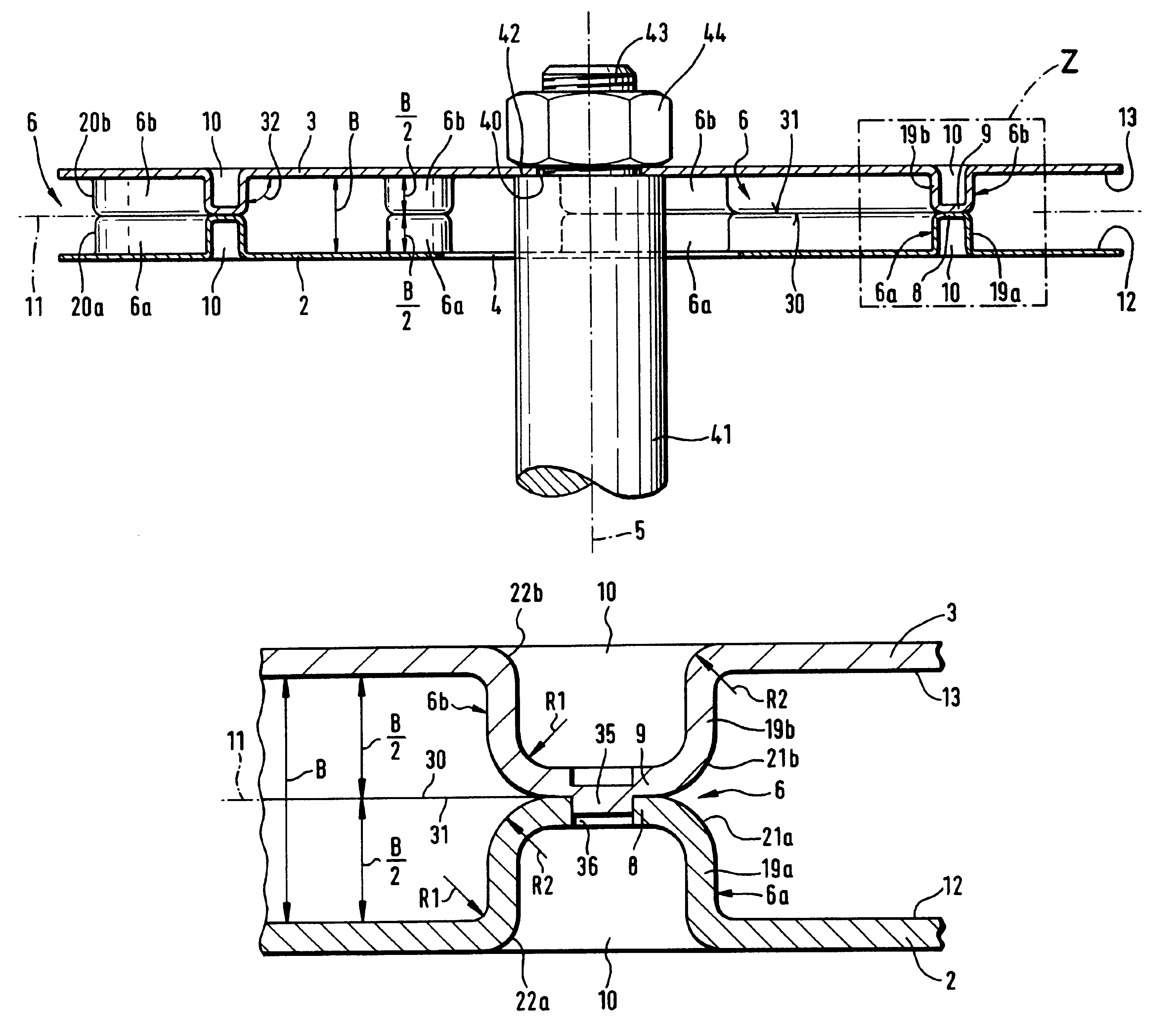
In FIG. 1 a plan view onto a fan wheel 1 for conveying an air mass is shown, as is used in particular in a turbo charger. The fan wheel according to the invention is also advantageously usable in other technological fields, for example, as a ventilator, a cooling air fan etc..

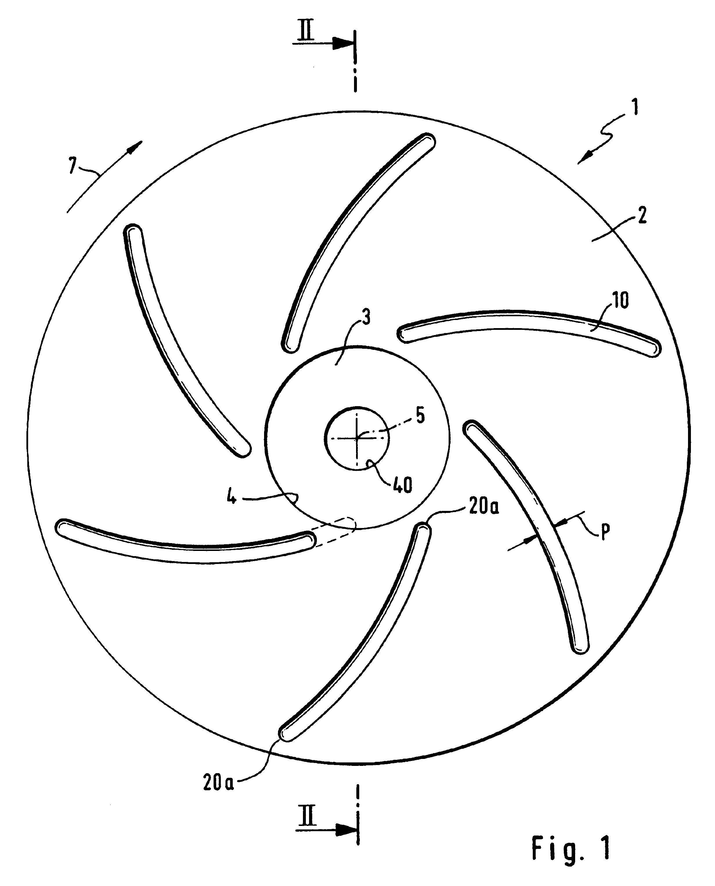
The fan wheel 1 is comprised essentially of two congruently positioned cover discs 2 and 3 which are parallel to one another in the shown embodiment and have a central opening 4 and 40, respectively, for connecting it, for example, to a hub. The central openings 4, 40 are positioned coaxially to the axis of rotation 5 of the base body or the fan wheel 1. The cover discs 2, 3 have advantageously the same material thickness; in the shown embodiment according to FIGS. 1 and 7, different material thickness (FIG. 2) is shown wherein the smaller opening 40 is provided in the cover disc 3 which is, for example, the thicker one. For attachment to the end of a shaft 41, the shaft 41 engages via the larger opening 4 the ...


PUM

PropertyMeasurementUnit
widthaaaaaaaaaa
widthaaaaaaaaaa
outer radiusaaaaaaaaaa

Abstract

The invention relates to a fan wheel for a turbo charger. The fan wheel (1) is comprised of a base body with a central axis of rotation (5) wherein the base body is assembled of two cover discs (2, 3) positioned approximately congruently opposite one another, between whose end faces (12, 13) facing one another fan blades (6) are arranged. The fan blades (6) are formed as monolithic parts on at least one of the cover discs (2, 3) and have an axial contact surface (30) against which an oppositely positioned axial contact surface (31) of the other cover disc (2,3) rests. Fastening means are provided in the area of the contact surfaces (8, 9) for non-detachably connecting the cover discs (2, 3) to one another. In order to produce the fan wheel (1) without balancing, the cover discs (2, 3) are embossed from a material that can be embossed and the fan blades (6) are embossed axially out of the material of a cover disc (2, 3), wherein the edge (22a, 22b) between the plane of the cover disc (2,3) and the sidewall (19a, 19b) of a fan blade (6) positioned substantially at a right angle to the plane of the cover disc (2, 3) as well as the edge (21a, 21b) between the sidewall (19a, 19b) of the contact surface (30, 31) are rounded with a radius (R1, R2) of approximately 0.5 to 2 mm.

Description

BACKGROUND OF THE INVENTION1. Field of the InventionThe invention relates to a fan wheel for conveying an air mass, especially for a turbo charger, ventilator or a similar device, comprised of a base body with a central axis of rotation, wherein the base body is comprised of two cover discs positioned approximately congruently opposite one another, between whose inner end faces facing one another fan blades are arranged which are formed as monolithic parts at least on one of the cover discs and have an axial contact surface against which an oppositely positioned axial contact surface of the other cover disc rests, and with fastening means in the area of the contact surfaces for non-detachably connecting the cover discs to one another.2. Description of the Related ArtSuch a known fan wheel is disclosed in DE 85 18 403. It is comprised of two cover discs approximately parallel to one another between which the fan blades are arranged. At one of the cover discs grooves are formed which ...

Claims


Application Information

Patent Timeline
Patent Type & Authority Patents(United States)
IPC IPC(8): F04D29/28F04D29/30
CPCF04D29/281F04D29/30Y10T29/49321F04D29/023F05D2230/54
Inventor STAHL, HERMANNWOLF, ERWIN
Owner HERMANN STAHL
Why Eureka
Try Eureka