Perpendicular magnetic recording medium and manufacturing process therefor

a technology of magnetic recording medium and manufacturing process, which is applied in the direction of magnetic materials for record carriers, light beam reproducing, instruments, etc., can solve the problems of reducing the perpendicular orientation of the perpendicular magnetic recording medium, reducing the perpendicular orientation of the perpendicular magnetic recording film, and poor surface smoothness of the soft magnetic underlayer film. , to achieve the effect of improving the perpendicular orientation of the perpendicular magnetizing film

Inactive Publication Date: 2002-05-14
WD MEDIA SINGAPORE PTE
View PDF16 Cites 91 Cited by
  • Summary
  • Abstract
  • Description
  • Claims
  • Application Information

AI Technical Summary

Benefits of technology

The perpendicular magnetic recording medium 120 of the embodiment has a Ti film or a non-magnetic CoCr film 122 between the soft magnetic underlayer film 116 and the pe

Problems solved by technology

However, such conventional perpendicular magnetic recording medium has limitation in lowering media noise and improving recording density dependence on read output voltage.
That is, poor surface smoothness of the soft magnetic underlayer film degrades the

Method used


Image

  • Perpendicular magnetic recording medium and manufacturing process therefor
  • Perpendicular magnetic recording medium and manufacturing process therefor
  • Perpendicular magnetic recording medium and manufacturing process therefor

Examples


first embodiment

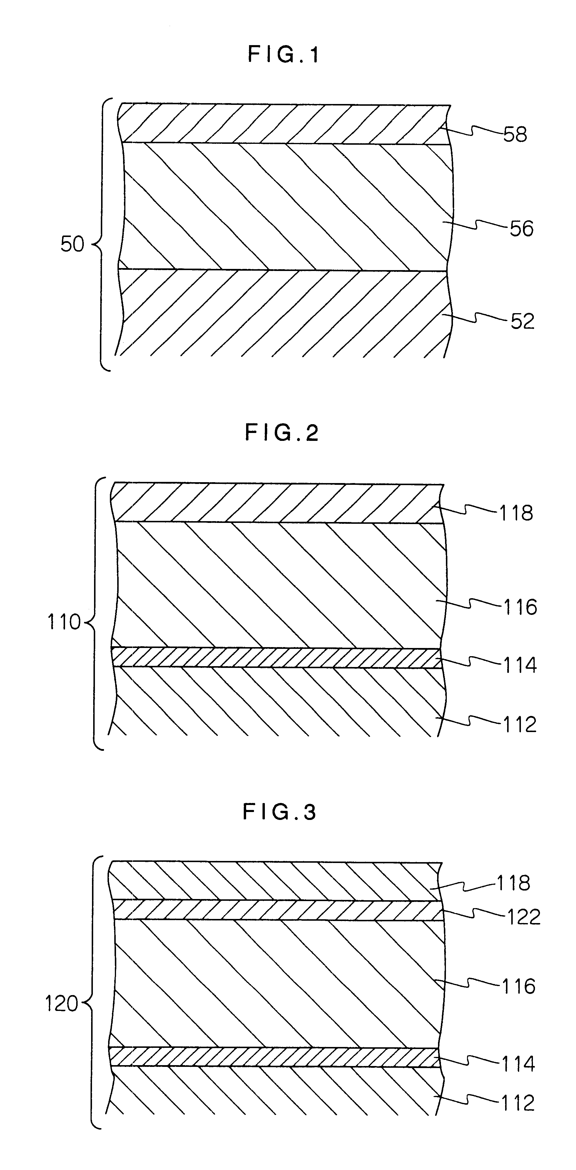
Now, there is described an example of the present invention (FIG. 2).

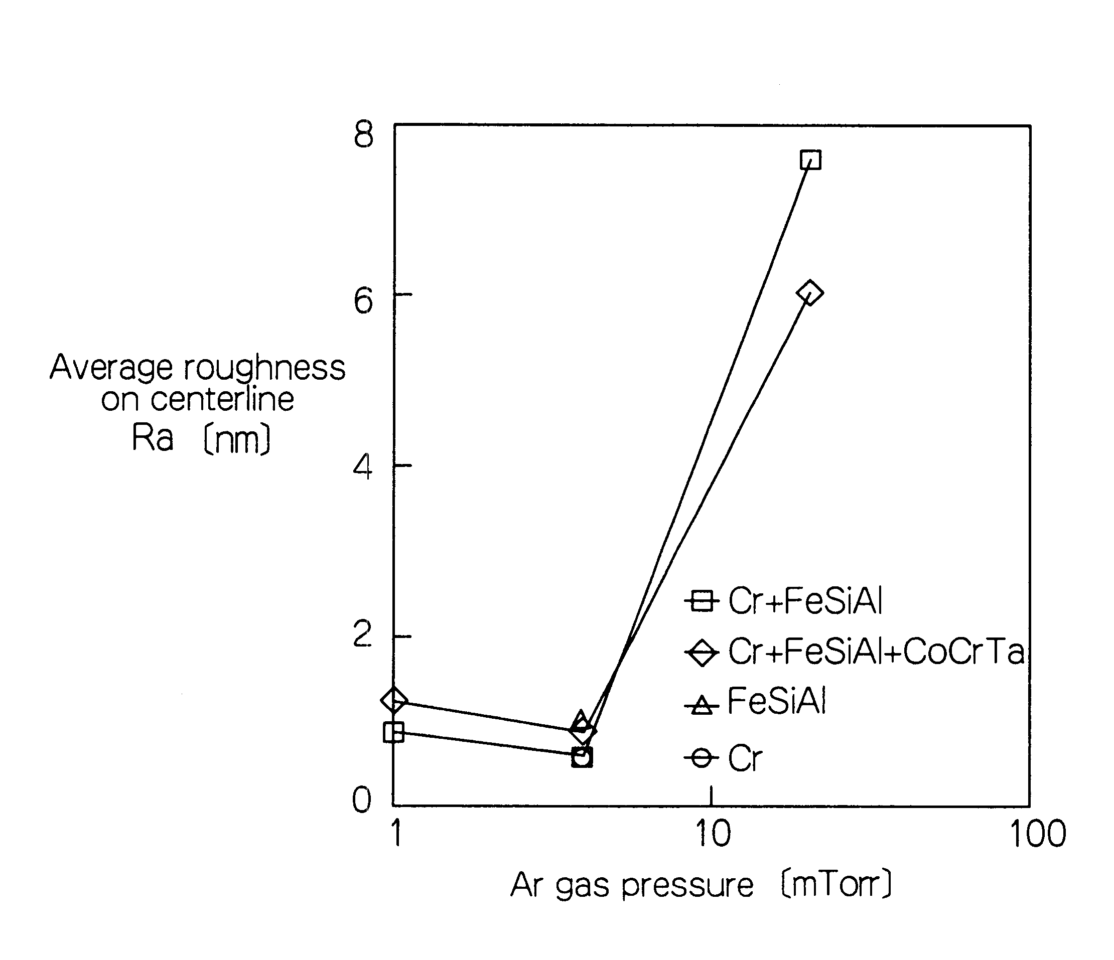
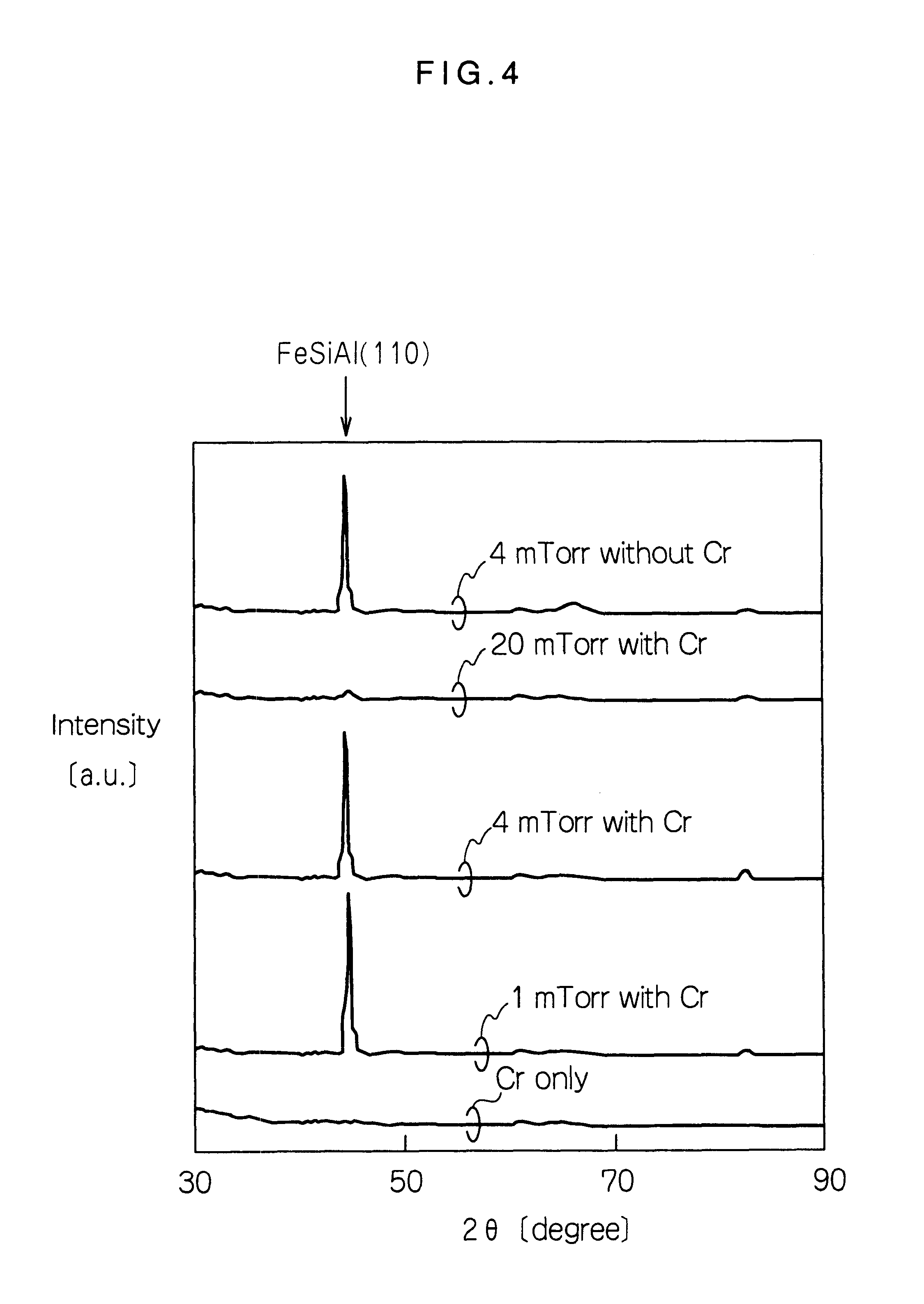
A Cr film 114, a soft magnetic underlayer film 116 and a perpendicular magnetizing film 118 were formed by a direct current magnetron sputtering device using Ar. First, the Cr film 114 was formed in a thickness of 11 nm using a Cr (3N) target with 6 inch diameter on a glass substrate 112 with 2.5 inch diameter. In this case, Ar gas pressure was 4 mTorr. Subsequently, the soft magnetic underlayer film 116 was formed in a thickness of 520 nm by using an Fe.sub.85 Si.sub.9.6 Al.sub.54.4 (wt %) target with 6 inch diameter on the Cr film 114. In this case, Ar gas pressure was three kinds of 1 mTorr, 4 mTorr, and 20 mTorr. Subsequently, the perpendicular magnetizing film 118 was formed in a thickness of 100 nm by using a Co.sub.78 Cr.sub.19 Ta.sub.3 (at %) target on the soft magnetic underlayer film 116. In this case, Ar gas pressure was 4 mTorr, while the substrate temperature was about 400.degree. C. Finally, a carbon ...

example 1

C films with thickness of 10 nm and 20 nm were formed on a 2.5-inch glass substrate using a C (3N) target with diameter of 6 inches by the sputtering process. Film formation conditions were supplied voltage 0.5 kW, argon gas pressure 4 mTorr and film formation speed 3 nm / sec under initial vacuum 5.times.10.sup.-7 mTorr. Then, an FeSiAl film was formed in 520 nm on each medium under the same film formation conditions using a Fe.sub.85 Si.sub.9.6 Al.sub.5.4 (wt %) target with diameter of 6 inches. Subsequently, a CoCrTa film was formed in 100 nm on each medium under the same film formation conditions using a Co.sub.78 Cr.sub.19 Ta.sub.3 (at %) target. Here, media inserted with the 10-nm C film and the 20-nm C film are called the inventive medium A1 and the comparative medium A2, respectively.

A half-width value of rocking curve (.DELTA..theta..sub.50) of hcp (002) peak was determined by using the X-ray diffraction to investigate perpendicular orientation of the perpendicular magnetizin...

example 2

Media using Ti in place of C in example 1 are called an inventive medium B1 and a comparative medium B2, respectively.

A half-width value of rocking curve (.DELTA..theta..sub.50) of hcp (002) peak was determined by using the X-ray diffraction similar to example 1 to investigate perpendicular orientation of the perpendicular magnetizing film of the inventive medium B1 and the comparative medium B2, FIG. 22 shows surface roughness Ra of each medium together with their values. As seen from FIG. 22, the surface smoothness of Ti film is significantly improved by reducing the thickness of Ti film, whereby the surface roughness of FeSiAl film can be improved. Then, it can be seen that, as the surface smoothness of the FeSiAl film is improved, the half-width value of rocking curve of hcp (002) peak of the CoCrTa film is reduced from 7.5 to 4.6, leading to improvement of the perpendicular orientation and surface smoothness of the perpendicular magnetizing film.

The inventive medium B1 and the ...


PUM


Abstract

It is intended to reduce the media noise, and to improve the recording density dependence of read output voltage. The present invention provides a perpendicular magnetic recording media and its manufacturing process, wherein a perpendicular magnetic recording medium comprises a soft magnetic underlayer film and a perpendicular magnetizing film, these films being formed on a substrate in this order, a smoothness control film such as Cr film, being inserted between the substrate and the soft magnetic underlayer film. Therefore, perpendicular orientation and surface smoothness are improved for the perpendicular magnetizing film laminated on the smooth surface of the soft magnetic underlayer film. As the perpendicular orientation is improved for the perpendicular magnetizing film, the initial layer is reduced, thereby media noise being lowered and recording density dependence of read output voltage being improved. In addition, as the surface smoothness is improved for the perpendicular magnetizing film, sliding characteristics of a recording/reproducing head is also improved, thereby this also lowering the media noise.

Description

1. Field of the InventionThe present invention relates to a perpendicular magnetic recording medium used as magnetic tape or a magnetic disk, and a process for manufacturing it.2. Description of the Prior ArtA magnetic disk is demanded for higher and higher surface recording density because a hard disk has higher and higher capacity and a smaller and smaller size accompanying with recent advancement of a personal computer or workstation. However, the longitudinal recording method which is widely used at present suffers from problems of thermal fluctuation from recording magnetization due to miniaturization of recording bit, and increase of coercive force which may exceed the recording capability of the recording head when it is intended to attain high-recording density. Thus, the perpendicular magnetic recording method is being studied as an approach which can significantly increase the surface recording density. It is a so-called double-layer perpendicular medium consisting of a so...

Claims


Application Information

Patent Timeline
IPC IPC(8): G11B5/73G11B5/84G11B5/66G11B5/62G11B5/851
CPCG11B5/66G11B5/667G11B5/851Y10T428/26Y10S428/90Y10T428/265G11B5/656G11B5/5521G11B2220/2516G11B5/676
Inventor HOKKYO, HIROTAKATSUBOI, SHINZO
Owner WD MEDIA SINGAPORE PTE
Why Eureka
Try Eureka