Semiconductor active fuse for AC power line and bidirectional switching device for the fuse

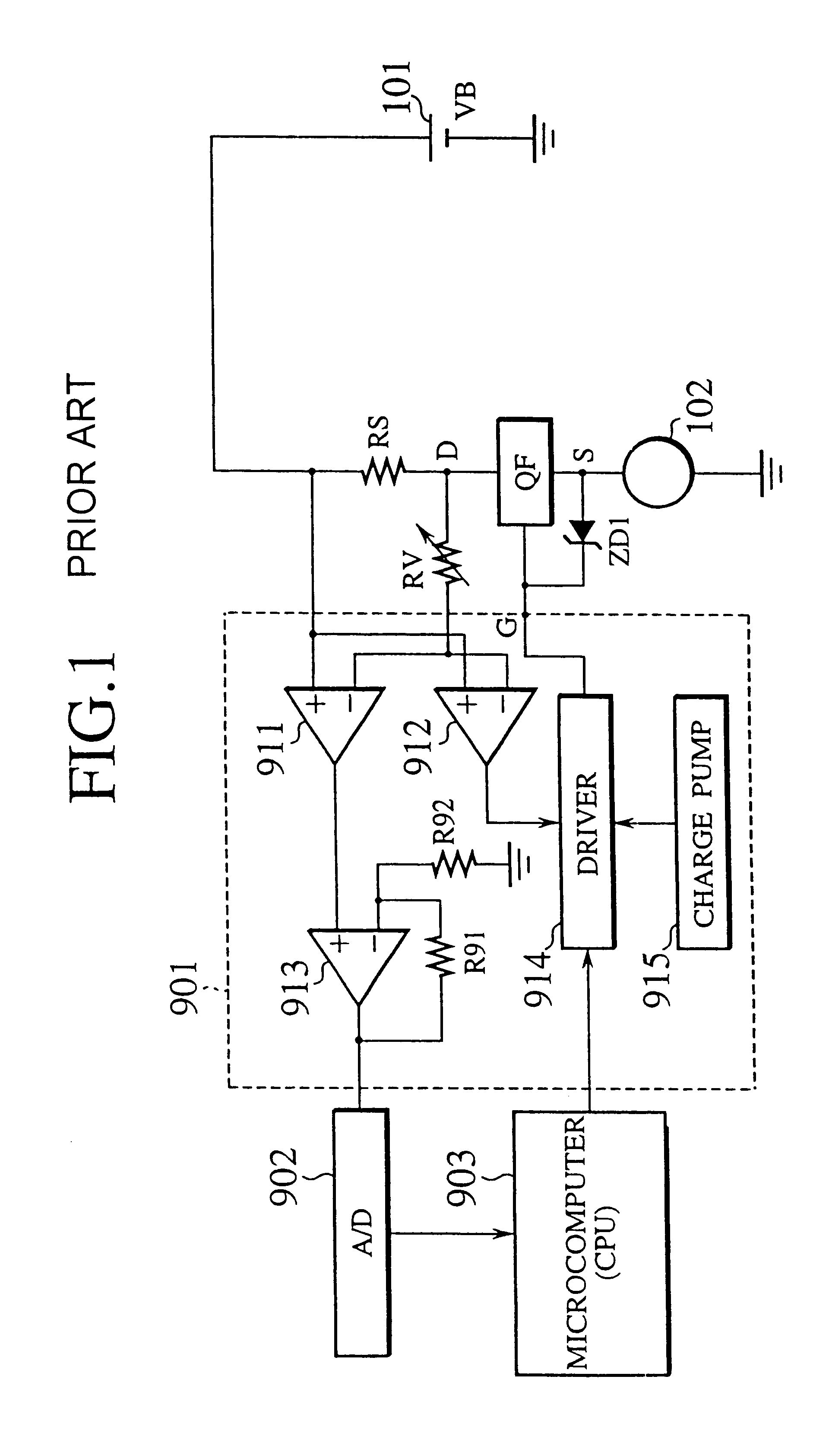
a technology of ac power line and active fuse, which is applied in the direction of electronic switching, emergency protective arrangements for limiting excess voltage/current, and pulse techniques, etc., can solve the problems of microcomputer 903 being expensive and slow to respond to such an abnormal current, and complicated and enlarge the supply/control apparatus

Inactive Publication Date: 2002-05-21
YAZAKI CORP
View PDF20 Cites 60 Cited by
  • Summary
  • Abstract
  • Description
  • Claims
  • Application Information

AI Technical Summary

Benefits of technology

Still another object of the present invention is to provide a bidirectional switching device that is easy to integrate and is manufacturable at low cost.
According to the third feature, the first main semiconductor element, first reference semiconductor element, second main semiconductor element, second reference semiconductor element first comparator, second comparator, and other related elements of the AC semiconductor active fuse may monolithically be integrated on a single semiconductor substrate, to reduce a packaging space. This enables the semiconductor active fuse to be mass-produced, to reduce the cost thereof. Alternatively, the first main and reference semiconductor elements and second main and reference semiconductor elements may be integrated into "a power chip", and the first and second comparators and other related elements may be integrated into "a control chip", to form a multi-chip module (MCM) or a hybrid IC of compact size.

Problems solved by technology

If a large current flows through the shunt resistor RS, the shunt resistor RS will cause a large heat dissipation The large heat dissipation is waste of electric energy and needs a cooler, which complicates and enlarges the supply / control apparatus.
However, the supply / control apparatus unsatisfactorily works on an incomplete short circuit failure having a certain extent of short-circuit resistance to produce a weak short-circuit current.
The microcomputer 903 is expensive and is slow to respond to such an abnormal current.
The shunt resistor RS, A / D converter 902, and microcomputer 903 that are imperative for the related art need a large space and are expensive, to increase the size and cost of the supply / control apparatus.
In addition to these problems, there is no related art that provides a bidirectional switching device or "an AC semiconductor active fuse" capable of operating on an AC power supply cable to disconnect the AC power supply cable upon detecting an abnormal current.
The reason why there is no bidirectional switching device or AC semiconductor active fuse is mainly because a control circuit for controlling a bidirectional switching device inserted in an AC power supply cable is difficult to design A control circuit for handling small signals usually operates on a voltage of, for example, 6 V, and it is very difficult to design a control circuit that withstands a commercial AC voltage of about 100-130 V Further difficulty lies in monolithically integrating a bidirectional switching device and its control circuit into a power device.
If there is an incomplete short circuit failure having a certain extent of short-circuit resistance in the power supply cable, the fall characteristic curves take a long time to converge below the predetermined voltage.

Method used


Image

  • Semiconductor active fuse for AC power line and bidirectional switching device for the fuse
  • Semiconductor active fuse for AC power line and bidirectional switching device for the fuse
  • Semiconductor active fuse for AC power line and bidirectional switching device for the fuse

Examples


Embodiment Construction

)

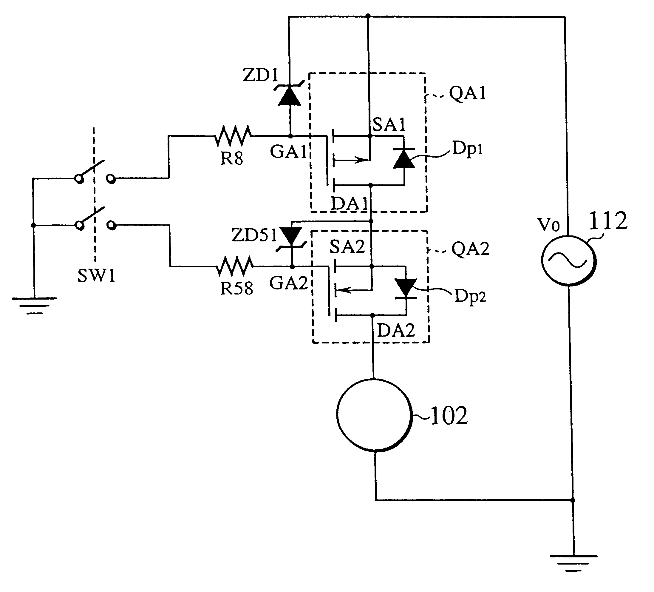
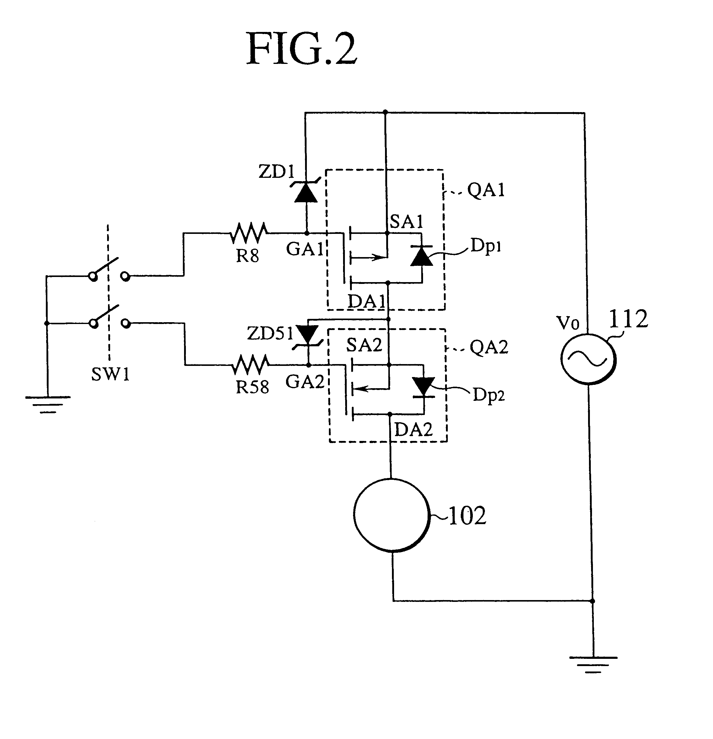
Various modifications will become possible for those skilled in the art after receiving the teachings of the present disclosure without departing from the scope thereof. For example, FIG. 10 shows a power IC according to still another embodiment of the present invention. The power IC consists of an n-channel first main semiconductor element QA11 and an n-channel second main semiconductor element QA2. The first main semiconductor element QA11 has a first main electrode DA1 connected to an ungrounded side of an AC power source 112, a second main electrode SA1 opposing to the first main electrode DA1, and a first control electrode GA1 for controlling a main current flowing between the first and second main electrodes The second main semiconductor element QA2 has a third main electrode SA2 connected to the second main electrode SA1, a fourth main electrode DA2 opposing to the third main electrode SA2 and connected to a load, and a second control electrode GA2 for controlling a main cur...


PUM


Abstract

A bidirectional switching device has a first main semiconductor element and a second main semiconductor element. The first main semiconductor element has a first main electrode connected to an ungrounded side of an AC power source, and a second main electrode. The first main semiconductor element contains a first parasitic diode whose cathode region is connected to the first main electrode and whose anode region is connected to the second main electrode. The second main semiconductor element has a third main electrode connected to the second main electrode, and a fourth main electrode connected to a load. The second main semiconductor element contains a second parasitic diode whose anode region is connected to the third main electrode and whose cathode region is connected to the fourth main electrode. A current flowing from the first main semiconductor element toward the second main semiconductor element passes through the second parasitic diode, and a current flowing from the second main semiconductor element toward the first main semiconductor element passes through the first parasitic diode. The bidirectional switching device is used to form a semiconductor active fuse for an AC power system. The semiconductor active fuse is capable of detecting an overcurrent without a shunt resistor, which was connected in series to a power supply cable, thereby minimizing heat dissipation as well as a conduction loss. The semiconductor active fuse is capable of easily and speedily detecting not only an overcurrent caused by a dead short but also an abnormal current caused by an incomplete short circuit failure having a certain extent of short-circuit resistance, and breaking alternating current in an AC power supply cable.

Description

1. Field of the InventionThe present invention relates to a bidirectional switching device for switching alternating current and an AC semiconductor active fuse employing the bidirectional switching device.2. Description of the Related ArtFIG. 1 shows a direct current supply / control apparatus according to a related art. The direct current supply / control apparatus has a switching element QF having a temperature sensor. The switching element QF controls the supply of power from a DC power source to a load. The DC power source 101 supplies a DC output voltage VB. The power source 101 is connected to an end of a shunt resistor RS. The other end of the shunt resistor RS is connected to a drain electrode D of the switching element QF whose source electrode S is connected to the load 102. The load 102 is, for example, a headlight or a power window motor of a vehicle. The bidirectional switching device also has a driver 901 for detecting a current flowing through the shunt resistor RS and c...

Claims


Application Information

Patent Timeline
Patent Type & Authority Patents(United States)
IPC IPC(8): H01L27/02H03K17/082H03K17/08H01L27/12
CPCH01L27/0248H03K17/0822H03K2017/0806H01L27/1203H01L24/49H01L2224/48137H01L2224/48247H01L2224/48464H01L2224/49175H01L2924/13091H01L2224/05599H01L2224/85424H01L2224/85444H01L2224/85447H01L2224/85455H01L2224/8546H01L2924/13055H01L2924/00014H01L2224/8547H01L2224/05554H01L24/45H01L2224/45124H01L24/48H01L2924/00H01L2924/013H01L2924/01026H01L2924/01024H01L2924/01028H01L2924/01014H01L2924/01027H01L2224/45015H01L2924/207
Inventor OHSHIMA, SHUNZOU
Owner YAZAKI CORP
Why Eureka
Try Eureka