Manifold system of removable components for distribution of fluids

a manifold system and fluid distribution technology, applied in the field of manifold systems, can solve the problems of large space, large amount of space, and high cost of gas panels, and achieve the effects of reducing production costs, reducing production costs, and reducing production costs

Inactive Publication Date: 2002-05-28
ICHOR SYST INC
View PDF41 Cites 113 Cited by
  • Summary
  • Abstract
  • Description
  • Claims
  • Application Information

AI Technical Summary

Problems solved by technology

The gas panel is located in the cabinet with the tool and typically occupies a relatively large amount of space, as each of the active devices are plumbed into the gas panel, either through welding tubing to the devices or combinations of welds and connectors such as VCR connectors available from Cajon Corporation or the like.
Gas panels are relatively difficult to manufacture and hence expensive.
Misalignment at a VCR fitting can result in leakage.
In addition, it has been found that VCR fittings often tend to come loose in transit and some gas panel manufacturers assume that the VCR fittings have loosened during transit, possibly admitting contaminants to the system.
Welds are relatively expensive to make in such systems but are typically carried out using a tungsten inert gas (TIG) system, having an orbital welding head to weld a tube stub and a tube together.
The welding must take place in an inert atmosphere, such as argon, and even then leads to deter

Method used


Image

  • Manifold system of removable components for distribution of fluids
  • Manifold system of removable components for distribution of fluids
  • Manifold system of removable components for distribution of fluids

Examples


first embodiment

In the manifold block, a central body portion can support a first upper flange and a second lower flange with complimentary configurations that are cantilevered from the central body portion. The size and position of the first upper flange and the second lower flange are such to compliment each other so that when they are interconnected by appropriate securement holes extending through the respective flanges, the common surface for their entrance and exit ports will be held in a common plane thereby ensuring an ease in sealing the passageway. One of the ports will extend onto the upper flange and into the central body of the manifold block. Self-aligning bore holes can be positioned on the upper flange to match complimentary threaded bores in a lower flange of an adjacent manifold block. Accordingly, threaded screws or bolts can self align and be used to interconnect adjacent manifold blocks with a simple tool such as an Allen wrench. The respective upper and lower flanges serve to ...

second embodiment

FIG. 6 is a perspective view of the present invention disclosing active component parts mounted on interconnect manifold blocks that are held together with connector plates;

FIG. 7 is an exploded view of the second embodiment disclosed in FIG. 6;

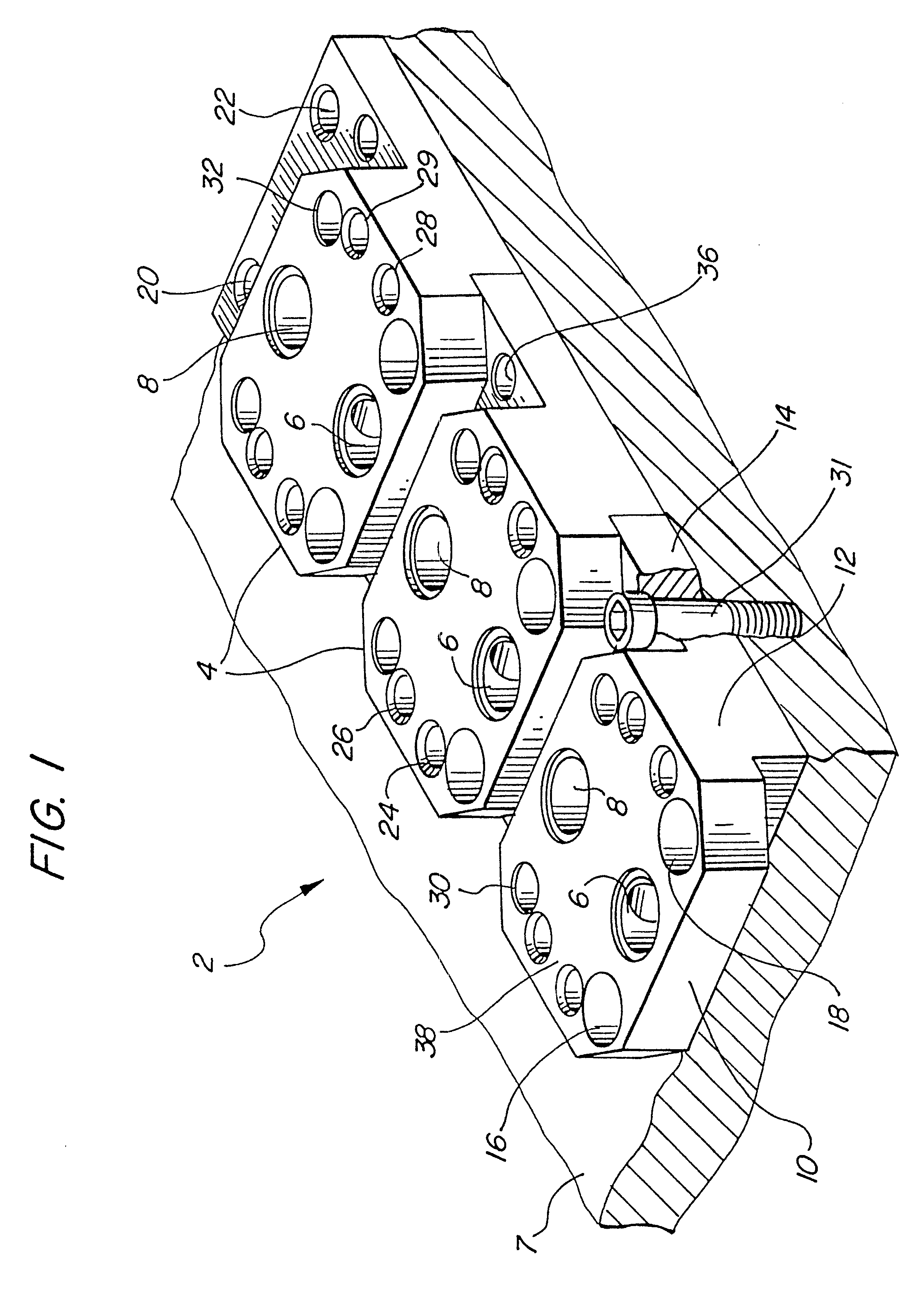
FIG. 8 is a third embodiment of the present invention disclosing an exploded view of interconnect manifold blocks of alternative configurations that can be held together by a series of connector plates;

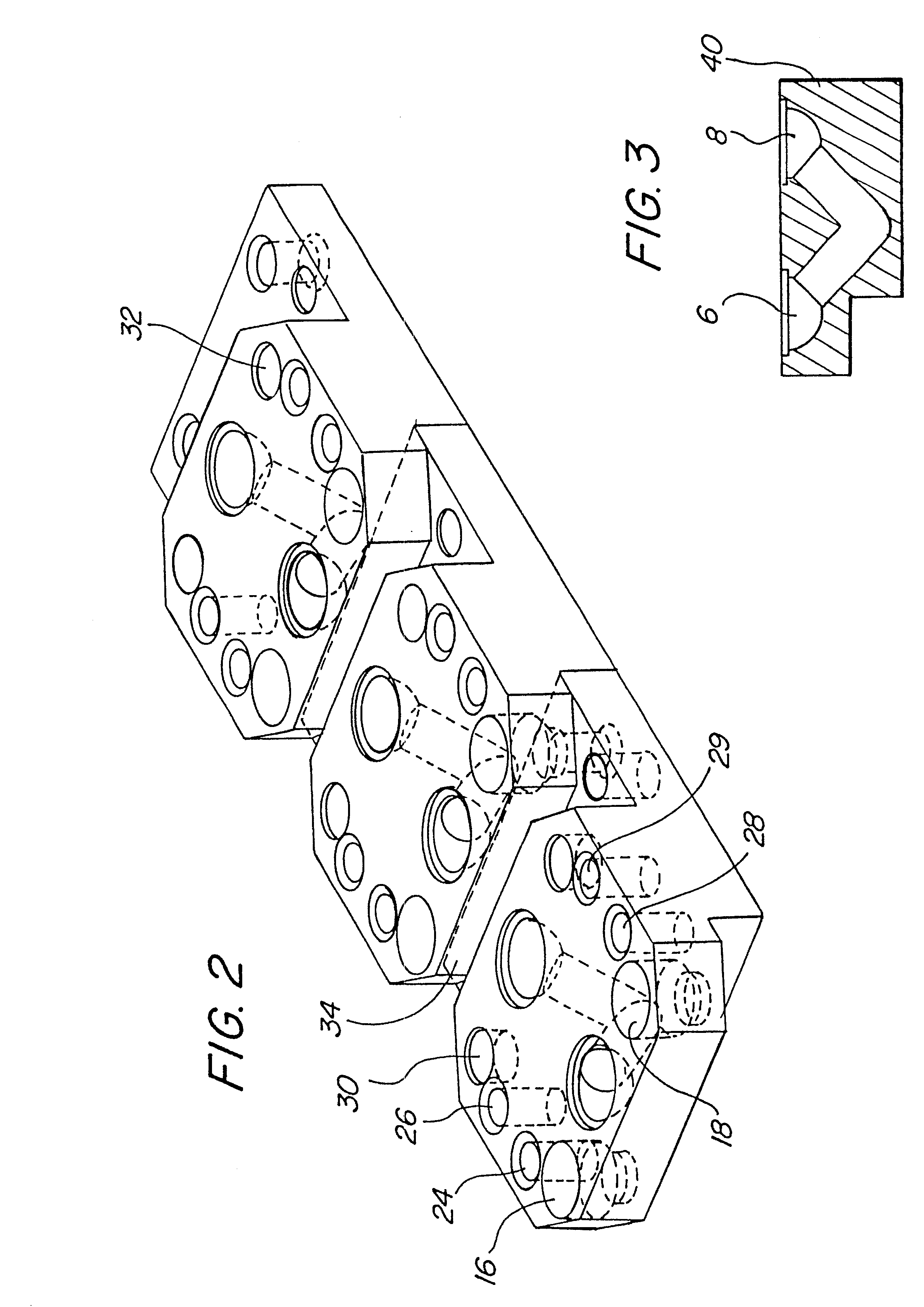
FIG. 9 is a cross sectional view of one of the manifold interconnect blocks of the third embodiment;

FIG. 10 is a bottom plan view of the embodiment of FIG. 9;

FIG. 11 is a perspective view of the fourth embodiment of the present invention;

FIG. 12 is an exploded view of FIG. 11;

FIG. 13 is a partial cross-sectional view of FIG. 11;

FIG. 14 is a plan view of a first manifold block of the fourth embodiment;

FIG. 15 is a plan view of a second manifold block of the fourth embodiment;

FIG. 16 is a plan view of a third manifold block of the fourth embodime...

third embodiment

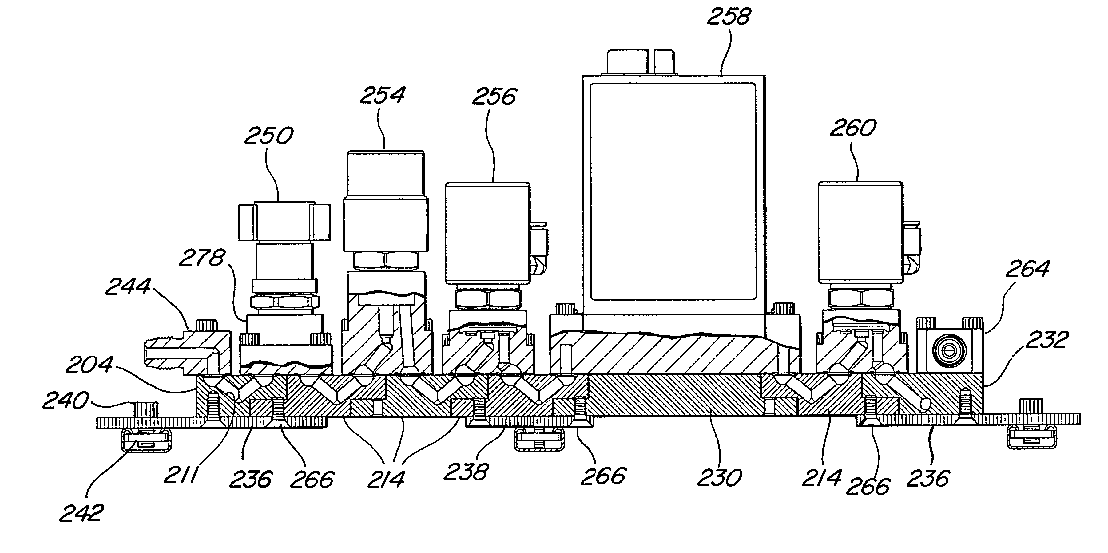
the present invention is disclosed in FIGS. 8, 9 and 10. FIG. 9 discloses a cross-sectional view of a manifold block 110. A plan view of the bottom side of the manifold block 110 is shown in FIG. 10 wherein a central rib member 112 accommodates the V-gas passageway. The connector plates 114 are appropriately notched 116 at each side of the connector plate 114 to thereby accommodate the rib projection 112. As shown in the exploded view of the gas stick in FIG. 8, a plurality of different manifold blocks can be used in this system starting with the L-shaped end manifold block 116, the subsequent adjacent manifold blocks 110, the T-shaped manifold block 118 and terminating with another end manifold block 116. Appropriate fastener bolts can be used to join the individual manifold blocks to the appropriate connector plates as previously described with appropriate keepers and seals.

As can be appreciated, each of the manifold blocks will have an entrance and exit port for accessing a commo...


PUM

PropertyMeasurementUnit
Depthaaaaaaaaaa
Heightaaaaaaaaaa
Distributionaaaaaaaaaa

Abstract

A manifold system for enabling a distribution of fluids includes a plurality of individual manifold blocks that can be joined together to form a gas stick. Each manifold block will have a fluid passage way with an entrance port and exit port accessing a common surface. An active component can be mounted to one manifold block, while extending across a port of an adjacent manifold block. An alignment system can be provided to ensure that the entrance and exit ports are positioned in a plane containing the common surface to facilitate sealing.

Description

1. Field of the InventionThe present invention is directed to a manifold system for enabling a distribution of fluids and more particularly, to a modular manifold system that is subjectively adaptable to semi-conductor processing equipment to enable a distribution of gases in a semi-conductor manufacturing environment by assembling a plurality of individual manifold blocks into a gas stick.2. Description of Related ArtWafer fabrication facilities are commnonly organized to include areas in which chemical vapor deposition, plasma deposition, plasma etching, sputtering and alike are carried out. In order to carry out these processes, it is necessary for the tools and machines that are used for the processes to be provided with a precise amount of processing gases to enable the fabrication steps. These gases can be inert, reactive, or can provide reactive species as desired by the particular manufacturing process.For instance, in order to perform epitaxial deposition, silicon tetrachlo...

Claims


Application Information

Patent Timeline
IPC IPC(8): C23C16/44F16K27/00F16K11/10F16K11/22H01L21/00H01J37/32F16L39/00H01L21/205H01L21/302H01L21/3065
CPCC23C16/44C23C16/45561H01L21/67017F16K27/003H01J37/3244F16K11/22Y10T137/87249Y10T137/87885
Inventor VU, KIM N.REDEMANN, ERIC J.SHERRIFF, DAVID P.
Owner ICHOR SYST INC
Why Eureka
Try Eureka