Multiplexer for cellular telephone

a multi-channel, cellular telephone technology, applied in the direction of waveguide type devices, elongated active element feeds, resonance antennas, etc., can solve the problems of inability to use antennas with cellular or cb transceivers, inability to achieve optimal am reception, and inability to achieve substantial loss or degradation of signals. , to achieve the effect of not affecting the signal quality

Inactive Publication Date: 2002-05-28
R A MILLIER IND INC
View PDF28 Cites 13 Cited by
  • Summary
  • Abstract
  • Description
  • Claims
  • Application Information

AI Technical Summary

Benefits of technology

These and other problems of the prior art are overcome by multiplex circuitry that provides for the reception and transmission of signals in different fre

Problems solved by technology

A problem in designing antennas of this type is to define an antenna which has near optimal receiving/transmission capabilities in several separate frequency bands.
Thus, there is a design conflict when a single antenna is used for several frequency ranges.
This has obvious disadvantages to the user of the radio, using impedance matching networks.
As a consequence, the lower frequency AM reception is not optimum but is acceptable.
However, such an antenna is unacceptable for use with a cellular or CB transceiver.
Similarly, a CB antenna does not provide adequate FM or cellular reception.
It is not feasible, however, to put separate AM/FM/WB, cellular and CB antennas on the mirrors because of space and interference considerations.
Consequently, these antennas have typically been placed in various locations on the vehicle with less than satisfactory signal reception or transmission.
For example, reception or transmission for FM and cellular telephone antennas mounted on the roof of a truck cab is often blocked by the box of the truck.
A significant problem in multiple antenna systems of the prior art is the mismatch in electrical characteristics between the two separate antennas of a dual antenna system and the mismatch between the antennas and the radio equipment.
Such mismatches result in a loss of power and can cause damage to the radio equipment due to reflected energy.
The loss of power is particularly noticeable in fiberglass cabs which lack the standard ground plane.
This is an approximate midpoint between the CB and FM band and does not provide optimal reception in the two separate bands.
The antenna, however, does not provide optimal reception of two separate frequency bands.
Such an arrangement with discrete capacitors is not practical for automotive antennas and other applications.
Such an arrangement does not provide the desired frequency band separation.
Such overlapping tubular section antennas work well as stationary antennas but are

Method used


Image

  • Multiplexer for cellular telephone
  • Multiplexer for cellular telephone
  • Multiplexer for cellular telephone

Examples


Embodiment Construction

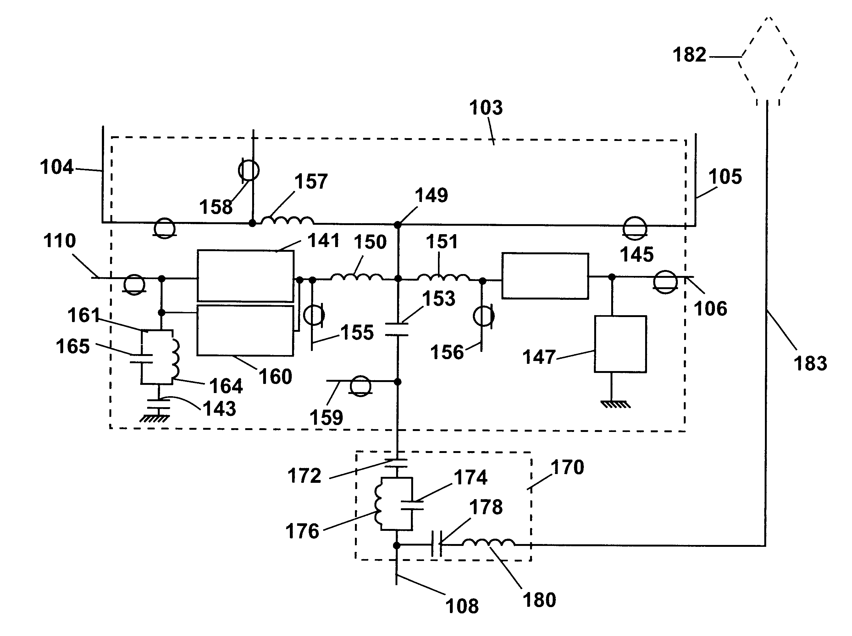
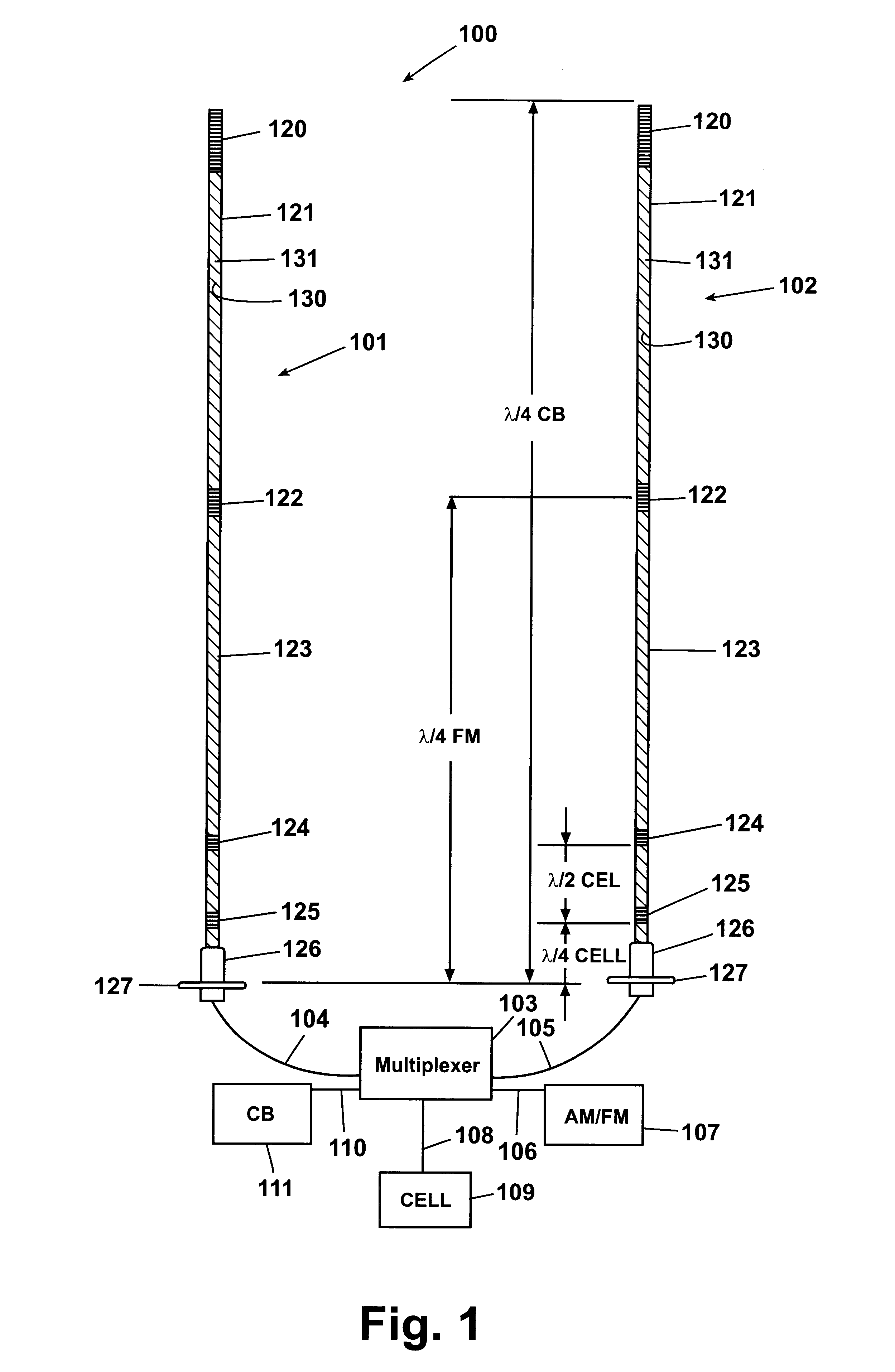
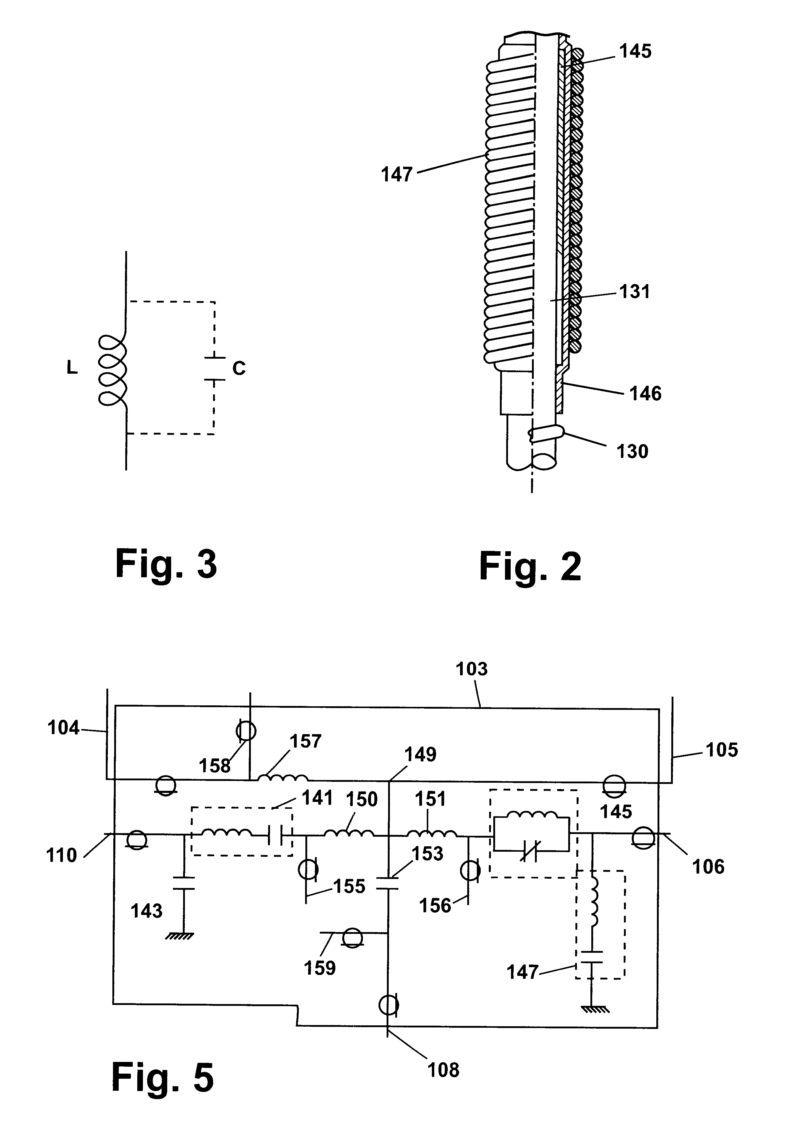
FIG. 1 shows an antenna system 100 comprising a pair of identical antennas 101, 102. The antennas 101, 102 are connected to a multiplexer 103 via conductors 104, 105, respectively. The multiplexer 103 serves to connect the antennas to an AM / FM receiver 107 via conductor 106, to cellular telephone equipment 109 via conductor 108 and to a CB transceiver 111 via conductor 110. Each of the antennas is mounted by means of a mounting nut 126 on a bracket 127 which may, for example, be a side mirror mounting bracket of a truck. The overall antenna is preferably on the order of 54 inches in length. The antennas each comprise an enamel coated conductive antenna wire 130 wound around an essentially cylindrically shaped core 131. The core 131 may be a solid core of fiberglass or the like material having a diameter of 1 / 4 inch. The wire of each antenna extends continually from the top of the core 131 to the mounting nut 126 where each antenna is connected to multiplexer 103 via one of the condu...


PUM


Abstract

A multiplexer circuit adapted to receive standard cellular telephone signals and PCS signals without user intervention comprises two filter circuits. The first filter circuit presents a high impedance to signals outside the standard cellular frequency range from one antenna and the second circuit presents a high impedance to signals outside the higher PCS frequency range from a second antenna. A cell phone adapted to receive both frequency ranges will automatically detect the appropriate signal.

Description

BACKGROUND OF THE INVENTION1. Field of the InventionThe invention pertains to antennas and multiplexers and more particularly to multiplexers for use with antennas and receiving apparatus operating in the FM, CB, weather band (WB) and cellular telephone frequency ranges.2. Prior ArtMultiband antennas that simultaneously serve as antennas for AM / FM broadcast radio and for Citizen Band transceivers are known. A problem in designing antennas of this type is to define an antenna which has near optimal receiving / transmission capabilities in several separate frequency bands. For example, the AM radio band falls in the comparatively low frequency range of 550 to 1700 kHz while FM radio operates in the 88 to 108 MHz range and CB operates in the relatively narrow range of 26.95 to 27.405 MHz. Cellular telephone operates in a frequency band of 825 to 890 MHz. It is well known from antenna design principles that a commonly used electrical length for a rod antenna used with a ground plane is on...

Claims


Application Information

Patent Timeline
IPC IPC(8): H01P1/20H01P1/213H04B1/48H04M1/03H04B1/44
CPCH03H7/463H01Q9/32H04B1/0057H01Q5/321
Inventor MILLER, PAUL E.SEWARD, GLEN J.BOGDANS, PAUL A.
Owner R A MILLIER IND INC
Why Eureka
Try Eureka