Magnetic support system

a support system and magnetic technology, applied in the field of support systems, can solve the problems of insufficient conventional approach, unsatisfactory application results, and known support systems with zero stiffness

Inactive Publication Date: 2002-06-11
ASML NETHERLANDS BV
View PDF11 Cites 24 Cited by
  • Summary
  • Abstract
  • Description
  • Claims
  • Application Information

AI Technical Summary

Benefits of technology

More in particular, it is an object of the present invention to provide a zero stiffness support system wherein there is no mechanical contact between the platform and the fixed world, wherein, in principle, no external energy is required for supporting, and wherein the system has a particularly simple and compact construction.

Problems solved by technology

This entails the problem that the platform must somehow be supported relative to a fixed world (floor), for instance for counteracting gravity, which fixed world is generally not free from vibrations.
However, this conventional approach yields insufficient result.
However, known support systems with zero stiffness have a number of drawbacks, as will be discussed in more detail hereinbelow.
As mentioned, the results achieved thereby are unsatisfactory for applications where high demands are imposed on the degree of being free from vibration.
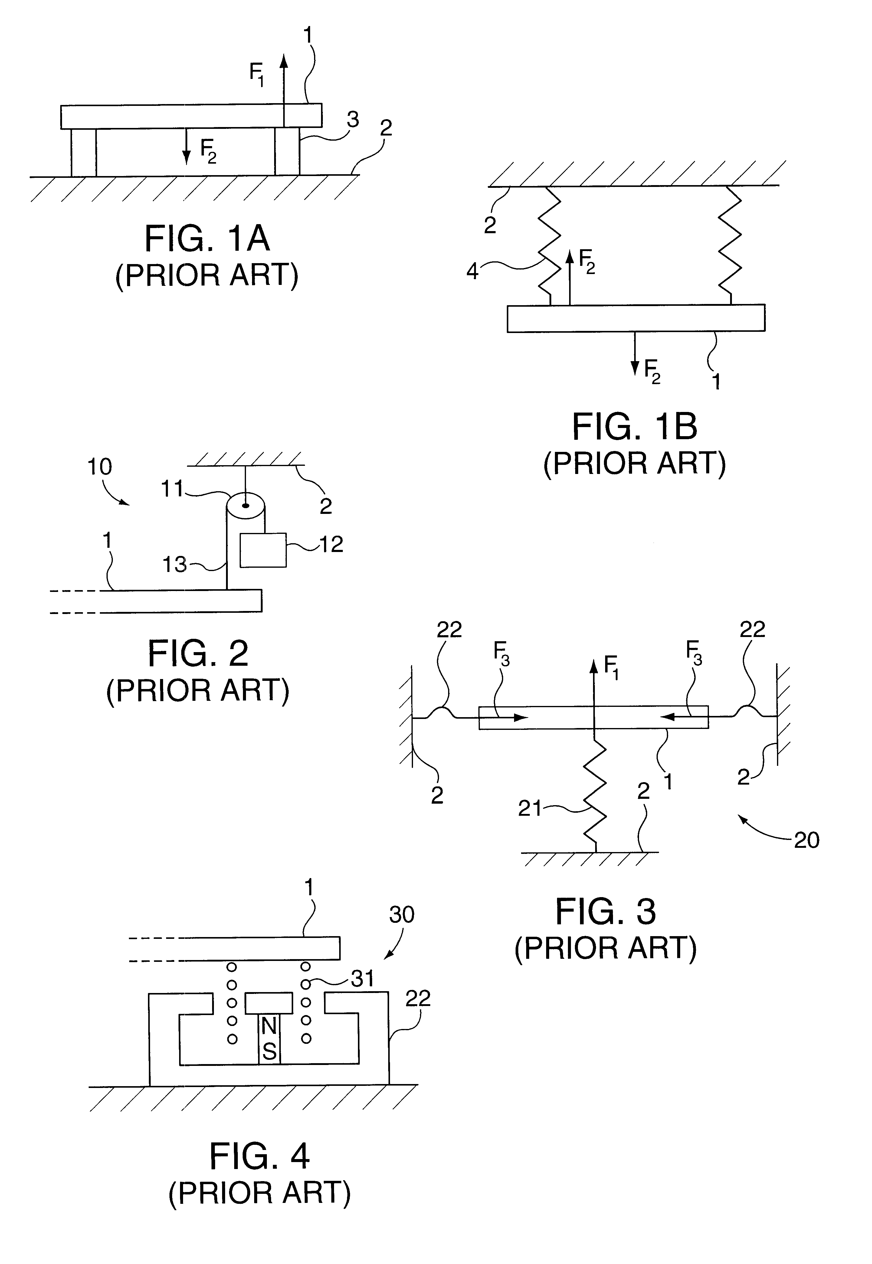
However, the arrangement of FIG. 2 is far from ideal, because vibrations in the fixed world 2 are directly transmitted to the platform 1 via the pulley 11 and the cable 13.
Further, it is a drawback that the space required for the counterweight and the pulley is fairly great.
Further, because of the manufacturing tolerances, it is particularly difficult to accurately predict the characteristics of the springs 21, 22 to be used, which means that the design of such bearing element 20 is particularly difficult, while reproducibility can hardly be realized, if at all.
An important drawback of this Lorentz arrangement is that it requires particularly much electric energy during use.
In addition, it is a drawback that during use, fairly much heat is produced, as a consequence of dissipation.
This requires a complicated, computer-controlled regulator, and the arrangement requires fairly much energy.
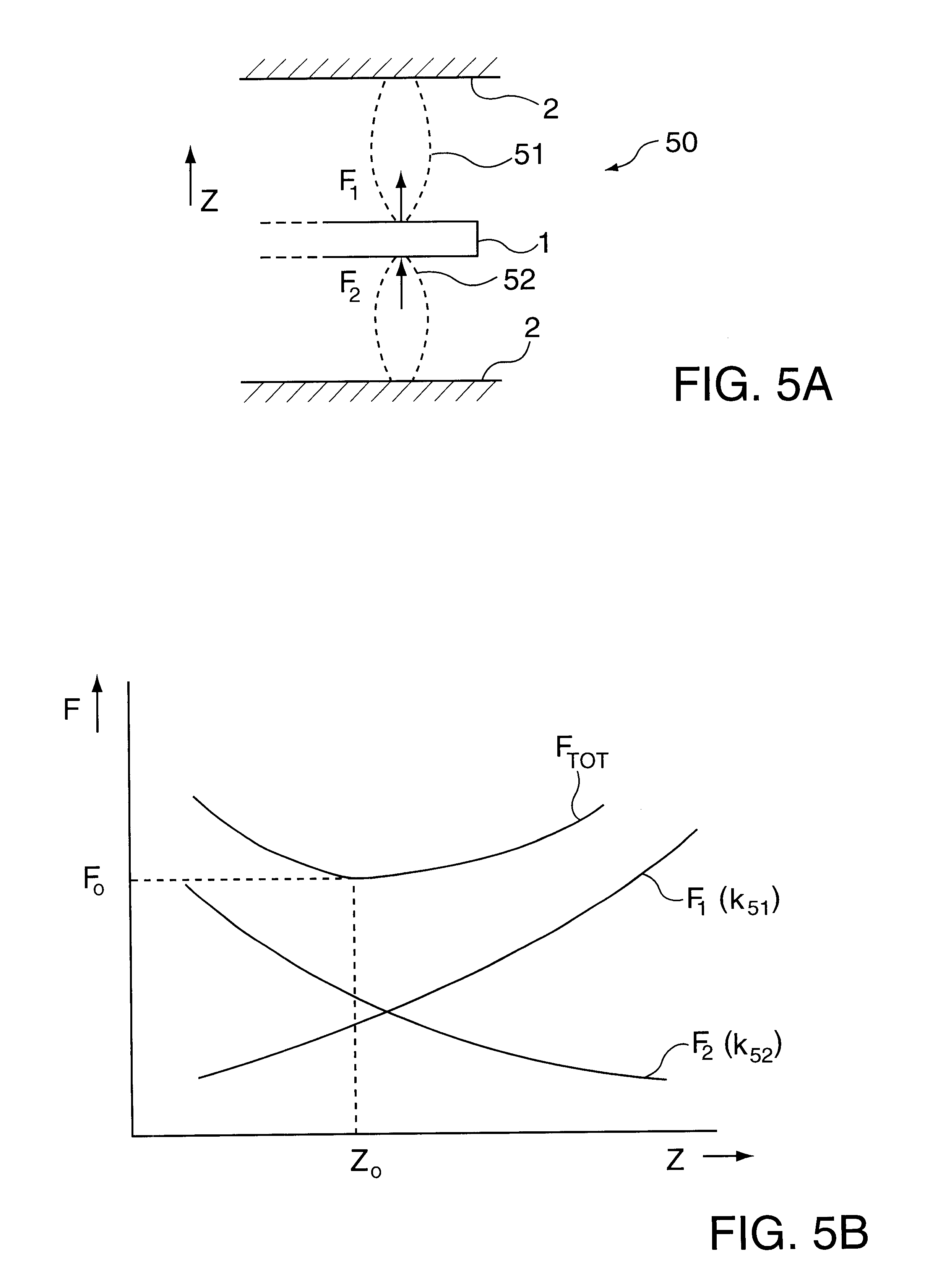
In practice, it will be difficult to operate the system exactly in that working point z.sub.0 ; once the system is outside the working point z.sub.0, it may drift further and further away from that working point, which is undesired.

Method used


Image

  • Magnetic support system
  • Magnetic support system
  • Magnetic support system

Examples


Embodiment Construction

FIG. 9 shows a schematic cross section of a practical realization of a bearing element according to the present invention. The two magnets 61 and 63 are standardly available NdFeB magnets having a disk shape and a circular section, having a diameter of 25 mm and a thickness (height) of 10 mm. The attraction member 65 is made from iron and likewise has a disk shape having a circular section, with a diameter of 72 mm and a thickness (height) of 10 mm.

For a conduction and concentration of the magnetic field lines, the lower magnet 61 is disposed in an iron beaker 91 whose bottom and wall have a thickness of 6 mm. The wall of the beaker 91 has an inside diameter of 32 mm. Arranged between the magnet 61 and the wall of the beaker 91 is a PVC positioning ring 92. For the same reason, the upper magnet 63 is disposed in an iron, annular container 93 having an inside diameter of 32 mm, an outside diameter of 50 mm and a height of 10 mm. Arranged between the upper magnet 63 and the annular co...


PUM


Abstract

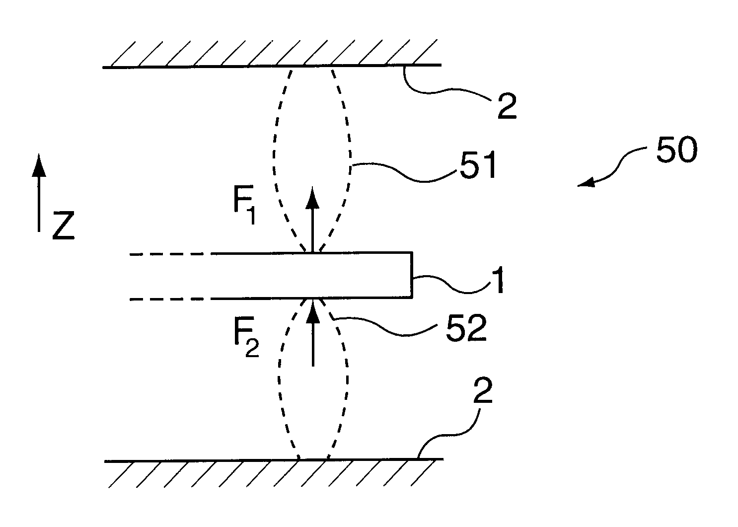
There is described a support system enabling supporting an object such as a platform (1) free from vibration, in that bearing elements (50) have a stiffness (k) which at a working point (z0) equals zero. A bearing element (50) comprises two magnectic couplings (51, 52) provided by permanent magnets (61, 63). One coupling (51) has a positive stiffness (k51), and the other coupling has a negative stiffness (k52); in the working point, the absolute values of those stiffnesses are equally great. Alternatively, electrostatic couplings are used.

Description

1. Field of the InventionThe invention relates to a support system in which an object can be supported free from vibration such that it can behave as if it floats freely, uncoupled from its environment. That object may be a platform or worktop or table, on which an experimenting arrangement can be built up, and the invention will therefore hereinafter be described for such a practical example. However, it will be understood that other practical examples are also possible, for instance specific parts in a positioning system.2. Description of the Related ArtAn important requirement imposed on such a platform is that the platform is positioned free from vibration, i.e. environmental vibrations must not be felt in the platform and the experimenting arrangement built thereon. This entails the problem that the platform must somehow be supported relative to a fixed world (floor), for instance for counteracting gravity, which fixed world is generally not free from vibrations.An important re...

Claims


Application Information

Patent Timeline
Patent Type & Authority Patents(United States)
IPC IPC(8): F16F6/00F16C39/06F16F15/03F16C39/00G01D11/00G01D11/14F16C32/04
CPCA47C31/003F16C39/063G01D11/14F16F15/03F16F6/005F16F6/00
Inventor NIJSSE, GERARD JOHANNES PIETERSPRONCK, JOSEPHUS WILHELMUS
Owner ASML NETHERLANDS BV
Why Eureka
Try Eureka