Method and apparatus for pressure washing

a pressure washing and pressure washing technology, applied in the direction of liquid displacement, vehicle cleaning, cleaning using liquids, etc., can solve the problems of chemical running off the roof and into the surrounding environment, contaminating the environment by man-made substances, and affecting the effect of cleaning

Inactive Publication Date: 2002-06-11
EZ ENVIRONMENTAL SOLUTIONS
View PDF53 Cites 53 Cited by
  • Summary
  • Abstract
  • Description
  • Claims
  • Application Information

AI Technical Summary

Problems solved by technology

Contamination of the environment by man-made substances has been considered a serious problem for a long time.
Both government regulations and social outcry have placed tremendous pressure on these businesses to avoid discharging hazardous wastes into the environment in the course of ordinary business activities.
Many businesses partake in activities which are likely to produce waste which may be harmful to the environment.
For example, in an automobile service station, washing or steam-cleaning auto parts, e.g., an automobile engine, often causes engine oil, gasoline, and other chemicals to enter a storm drain system, or other waterways, thereby leading to the potential contamination of groundwater.
In addition, those who service remotely located equipment generally have a need to wash the equipment without discharging hazardous waste into the environment.
By way of example, persons who service roof-mounted air conditioners that contain lubricating petrochemicals, trapped pollutants, or other chemicals are not permitted to wash the equipment in a manner that could cause chemicals to run off the roof and into the surrounding environment.
However, many pressure washers do not have containment capability for hazardous materials.
Hence, such pressure washers may not prevent hazardous materials from entering the surrounding environment.
Some pressure washers may be able to recover some wash fluid, although pressure washers which recover some wash fluid often do not filter hazardous wastes, or do not efficiently filter all hazardous wastes out of the wash fluid.
As such, pressure washing systems often generate relatively large volumes of wastewater which must either be processed separately, or placed in barrels for disposal.
Further, since such pressure washing systems are often required to handle large volumes of wastewater, the pressure washing systems are not readily moved.

Method used


Image

  • Method and apparatus for pressure washing
  • Method and apparatus for pressure washing
  • Method and apparatus for pressure washing

Examples


first embodiment

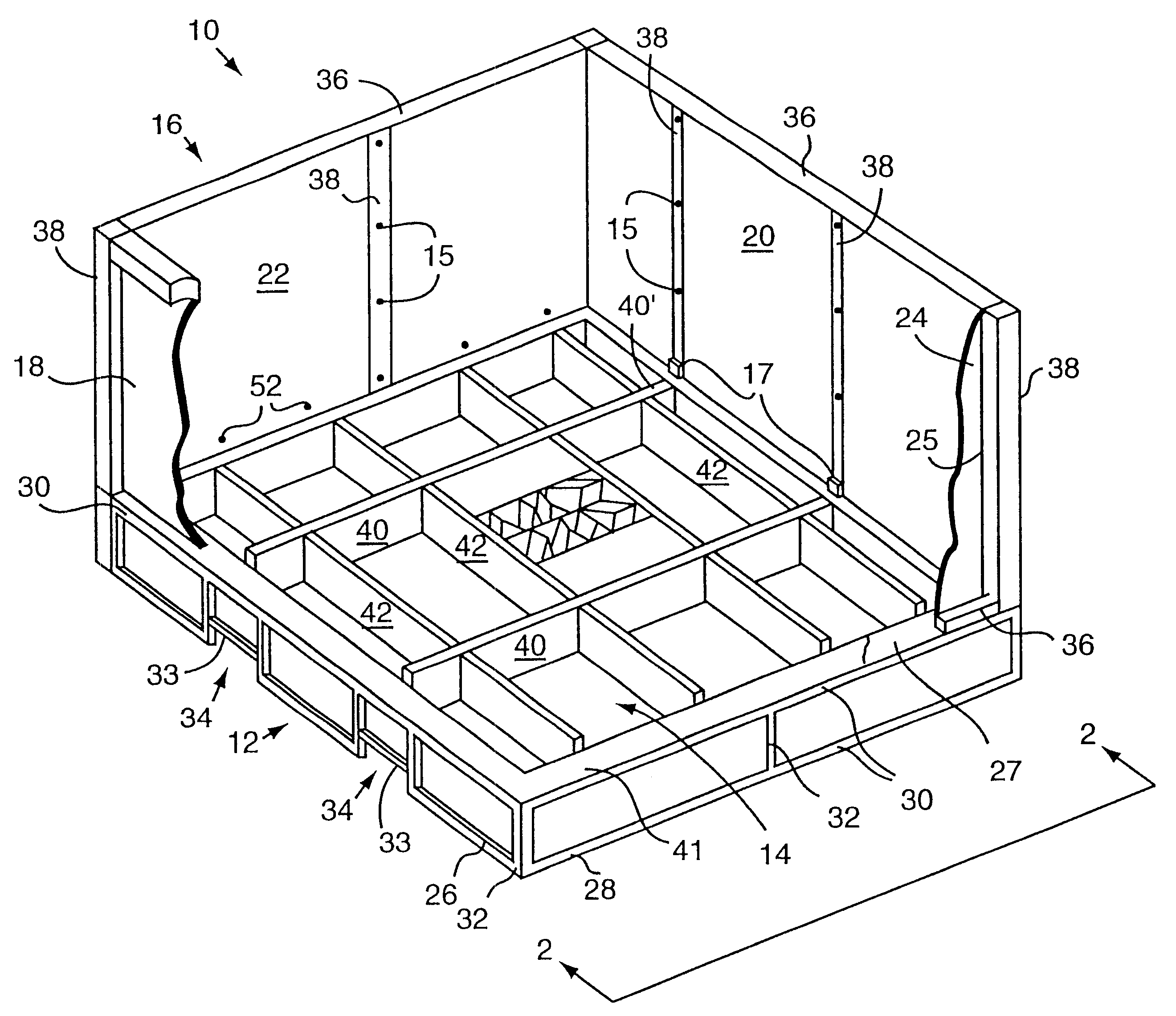
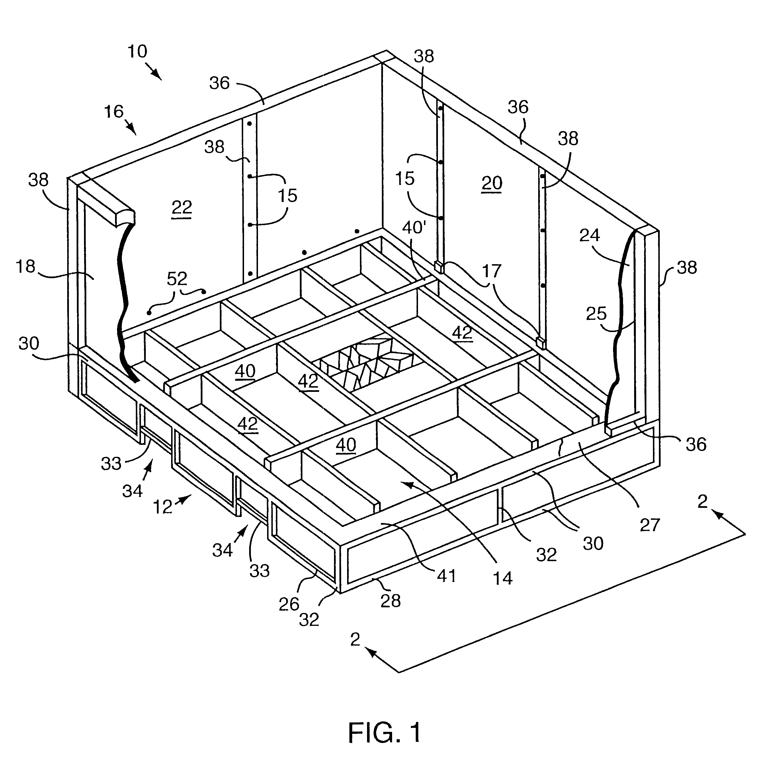
FIGS. 1, 2, and 3 show a pressure washing apparatus, or wash rack, 10 which includes a base frame 12, a containment tub 14, and a wall frame 16 in accordance with the present invention. Front and rear walls 18, 20 and left and right-side walls 22, 24 are affixed to wall frame 16, thereby forming a rectangular enclosure into which an object is placed for washing. It should be appreciated that in FIG. 1, the front wall 18 and right wall 24 are shown in cutaway, in order to enable details of the tub to be shown.

The base frame 12 is a generally rectangular structure comprising four base side frames, although it should be appreciated that base frame 12 may take on any suitable shape. A front base side frame 26 and a right base side frame 28 are shown in FIG. 1. It should be appreciated that similar rear and left base side frames are also provided. Each of the base side frames is formed from horizontal beams 30 that are joined to vertical posts 32. The beams 30 and posts 20 may be welded ...

second embodiment

FIG. 9 is a top view of a beam, or baffle, arrangement in a washing apparatus with debris filters in accordance with the present invention. When objects to be washed in the washing apparatus are particularly soiled, in addition to contaminants, debris may be washed from the objects. Debris may include heavy particles such as, by way of example, metal shavings and rubber residue. The gap that is provided on three sides of the subfloor placed in the washing apparatus, as described above with respect to FIG. 3, enables washing fluid and debris to flow into the tub. The debris may settle on the floor of the tub, as mentioned above with respect to FIG. 4. However, in one embodiment, debris filters or "gutters," which serve to capture at least some of the debris as it flows through the gap on the sides of the subfloor, may be added to the washing apparatus.

Beams 40, 442 rest in tub 14, and fit snugly against one another to form a plurality of containment compartments A, B, C, D, E, F, G, ...

third embodiment

The organization of beams in a washing apparatus, as well as the relative location of openings in the beams, may also be varied. For example, with reference to FIG. 10, a beam arrangement within a tub will be described. Baffles 520, 524 are arranged within tub, or basin, 514 such that baffles 520, 524 interlock with respect to one another to define a plurality of compartments M, N, O, P, Q, R, S, and T within tub 514. In the described embodiment, baffles 520, 524 substantially abut sides 528 of tub 514. That is, each end of each baffle 520, 524 abuts a side 528 of tub 514.

To ensure that there is substantially no gap between baffles 520, 524, and sides 528 of tub 514, the ends of baffles 520, 524 are generally attached, e.g., welded, to sides 528 of tub 514. Portions of baffles 520, 524 which contact the bottom of tub 514 are typically also welded to ensure a seal between baffles 520, 524 and the bottom of tub 514. Such a seal essentially prevents water in one chamber from accidental...


PUM

PropertyMeasurementUnit
heightaaaaaaaaaa
heightaaaaaaaaaa
depthaaaaaaaaaa

Abstract

The present invention relates to methods and apparatus for removing a contaminant from an object. According to one aspect, an apparatus for washing an object which has contaminant is arranged to recover the contaminant. The apparatus includes a support floor that supports an object to be washed and a basin mounted below the support floor. The basin is divided into a plurality of chambers which include a clean water chamber, a secondary water chamber, an oil containment chamber, and a contaminated water receiving chamber which receives water which is contaminated after it is flowed over the object to remove the contaminant. The contaminated water received in the contaminated water receiving chamber must pass sequentially through the oil containment chamber and the secondary water chamber prior to entering the clean water chamber. The clean water chamber is flowably coupled to the secondary water chamber by a first flowpath near the operational water level, while the secondary water chamber is flowably coupled to the oil containment chamber by a second flowpath near the bottom of the basin. The oil containment chamber is flowably coupled to the contaminated water receiving chamber by a third flowpath near the operational water level. The apparatus also includes a first pump which draws and filters water from the secondary water chamber and returns the filtered water to the clean water chamber.

Description

This application claims the benefit of U.S. Provisional Application No. 60 / 065,864, filed Nov. 14, 1997, and is related to co-pending U.S. patent application Ser. No. 08 / 732,638 filed Oct. 15, 1996 now U.S. Pat. No. 5,785,067, and co-pending U.S. patent application Ser. No. 08 / 813,919 filed Mar. 7, 1997 now U.S. Pat. No. 5,803,982, which are incorporated herein by reference in their entirety.1. Field of InventionThe present invention relates generally to methods and apparatus for use in pressure washing. More particularly, the present invention relates to methods and apparatus for safely washing objects with a pressure washer, or similar device, and recovering contaminants from the objects.2. Description of the Relevant ArtContamination of the environment by man-made substances has been considered a serious problem for a long time. Recently, concern about contamination of earth, air, and groundwater by oil, toxic chemicals, and other hazardous wastes has expanded beyond large-scale ...

Claims


Application Information

Patent Timeline
Patent Type & Authority Patents(United States)
IPC IPC(8): B08B3/02B08B3/00B08B3/14B60S3/00B08B3/04B08B3/08B08B3/10B08B17/00C02F1/78
CPCB08B3/006B08B3/026B60S3/00B08B17/00B08B17/025B08B3/14
Inventor DAMRON, MICHAEL D.GARCIA, EDUARDO M.ELIASON, SCOTTDRISCOLL, JR., RUDOLPH W.
Owner EZ ENVIRONMENTAL SOLUTIONS
Why Eureka
Try Eureka