Transmit baseline wander correction technique

a correction technique and baseline technology, applied in the direction of transmission line coupling arrangement, automatic control, transmitter/receiver shaping network, etc., can solve the problem of baseline wander, data errors, jitter or data loss

Inactive Publication Date: 2002-06-18
PMC-SIERRA
View PDF3 Cites 48 Cited by
  • Summary
  • Abstract
  • Description
  • Claims
  • Application Information

AI Technical Summary

Problems solved by technology

When transmitting data from a transmitter to a receiver, bandpass limitations can cause a phenomenon called baseline wander, which is the shifting of a central e.g. neutral, voltage or current value about which data signal excursions occur, positively or negatively from the proper neutral or central value.
As will be described below, this can cause jitter or data loss.
For multi-level (Pulse Amplitude Modulated or PAM) codes, however, where there are multiple thresholds required to resolve the transmitted symbol, the effects can be catastrophic and result in data errors.
It is difficult to manufacture transformers with wide frequency responses (i.e. K close to 1), so when attempting to transmit high data rates, designers are forced to use transformers with the minimum OCL that they can.
Other standards, such as 155Mbit/s ATM and 100 BaseT Ethernet may also suffer from BLW "killer packets", but this is a matter of some debate.
Depending on the complexity of the rest of the equalizer, this may be easy or difficult.
This is, in theory, the simplest to conceive; however the BLW correction algorithm in ...

Method used


Image

  • Transmit baseline wander correction technique
  • Transmit baseline wander correction technique
  • Transmit baseline wander correction technique

Examples


Embodiment Construction

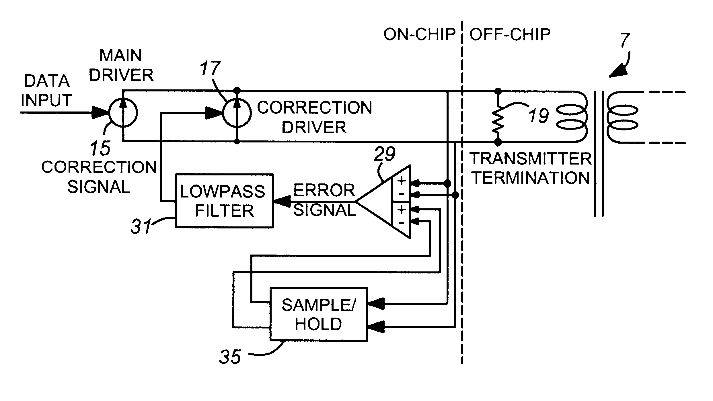
Turning to FIG. 5, a main current driver 15 receives a digital data input signal at a control input, and drives a primary winding of a transformer 7, which winding is in parallel with a transmitter termination resistor 19. A correction (compensation) current driver 17 has a correction signal applied to its control input, the correction signal being derived from the output of error amplifier 29 via lowpass filter 31.

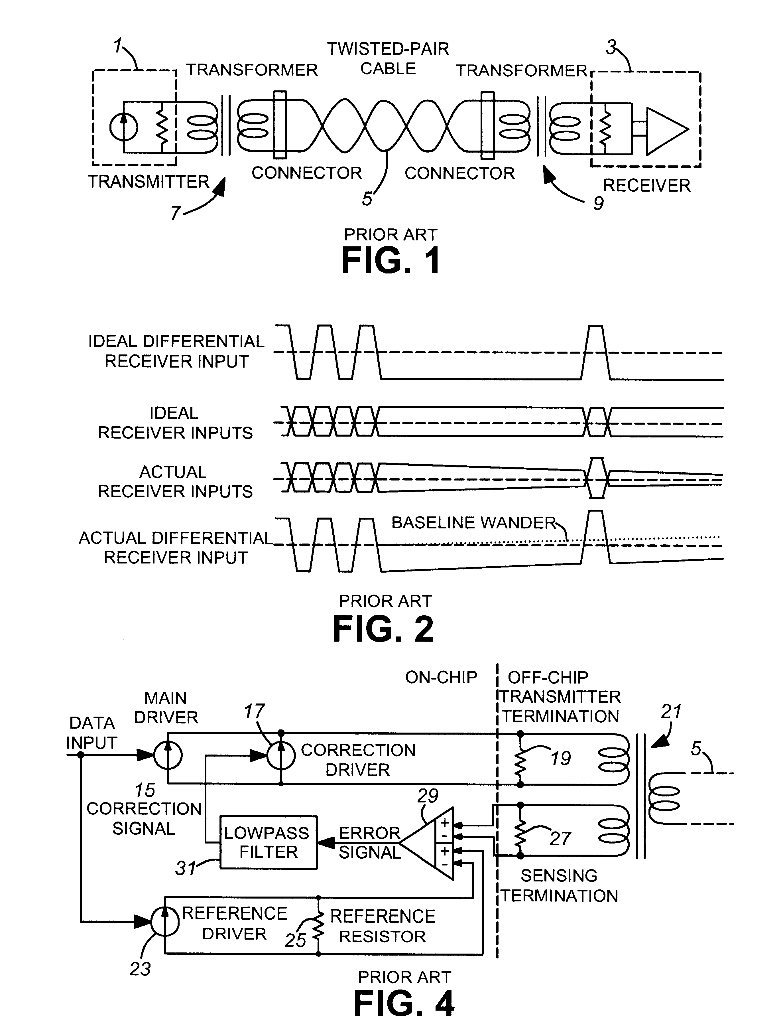
So far, except for the type of transformer used, the circuit is similar to that of FIG. 4.

However, in this embodiment of the invention, instead of one of the signals applied to a pair of inputs of the error amplifier 29, e.g. a comparator, being obtained from a ternary winding of the transformer, it is obtained from directly across the primary winding of the transformer. The same signal is applied to the input of a sample and hold circuit 35. The ongoing signal is thus sampled from time to time (preferably in sync with the input signal) and is held by circuit 35.

The outpu...


PUM


Abstract

A circuit for correcting baseline wander in a transmitter which includes a main signal current driver driving a first winding of a two-winding transformer which first winding is in parallel with a termination impedance matching load, in which a compensation current driver is coupled in parallel with the main signal current driver for adding its current to current of the main signal current driver. A correction signal control input is provided to the compensation driver. A sample-and-hold circuit is connected across the first winding, an error amplifier having a first pair of inputs is connected across the first winding and a second pair of inputs are connected to the output of the sample and hold circuit. These provide an error signal resulting from a difference of signals appearing at its respective pairs of inputs. A circuit is provided for applying the error signal to the correction signal control input of the compensation current driver, whereby any difference between a present signal carried by the first winding of the transformer, and a past signal held by the sample-and-hold circuit, results in an error signal and generation of a correcting current by the compensation current driver so as to substantially eliminate the difference.

Description

This invention relates to the field of digital data transmission, and particularly to a method of compensating for baseline wander in a transformer coupled transmission link.BACKGROUND TO THE INVENTIONWhen transmitting data from a transmitter to a receiver, bandpass limitations can cause a phenomenon called baseline wander, which is the shifting of a central e.g. neutral, voltage or current value about which data signal excursions occur, positively or negatively from the proper neutral or central value. As will be described below, this can cause jitter or data loss.With reference to FIG. 1, a schematic diagram is shown as a Norton equivalent circuit, which includes a transmitter 1 comprising a current driver, which may, depending on the network standard, be as simple as an on / off switch or as complex as a linear driver or a Digital-to-Analog Converter (DAC). A receiver 3 (shown as an amplifier) may be as simple as an error amplifier or as complex as a full analog adaptive equalizer....

Claims


Application Information

Patent Timeline
IPC IPC(8): H04L25/08
CPCH04L25/085H04L25/0266
Inventor LYE, WILLIAMCANDAGE, ANTHONY B.
Owner PMC-SIERRA
Why Eureka
Try Eureka