Continuous hydrosilylation method for production of a modified liquid organosilicon compound

a technology of liquid organosilicon and hydrosilylation method, which is applied in the direction of liquid degasification, rotary stirring mixer, separation process, etc., can solve the problems of reducing the efficiency of the whole process, significantly prolonging the reaction time, and often taking an extremely long time to rea

Inactive Publication Date: 2002-06-25
DOW TORAY CO LTD +1
View PDF4 Cites 43 Cited by
  • Summary
  • Abstract
  • Description
  • Claims
  • Application Information

AI Technical Summary

Problems solved by technology

In order to satisfy such requirements, the reaction often took an extremely long time.
Since the use of such a solvent presents a danger from the point of view of fire or explosion, special measures have to be undertaken for the removal of the organic solvent after completion of the reaction.
This decreases the efficiency of the process as a whole.
Such a method, however, significantly prolongs the reaction time.
Such a method, however, does not solve the problems of the prior art since the process remains essentially a batch-type process.

Method used


Image

  • Continuous hydrosilylation method for production of a modified liquid organosilicon compound
  • Continuous hydrosilylation method for production of a modified liquid organosilicon compound
  • Continuous hydrosilylation method for production of a modified liquid organosilicon compound

Examples


example 1

Practical Example 1

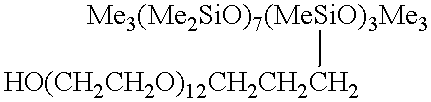
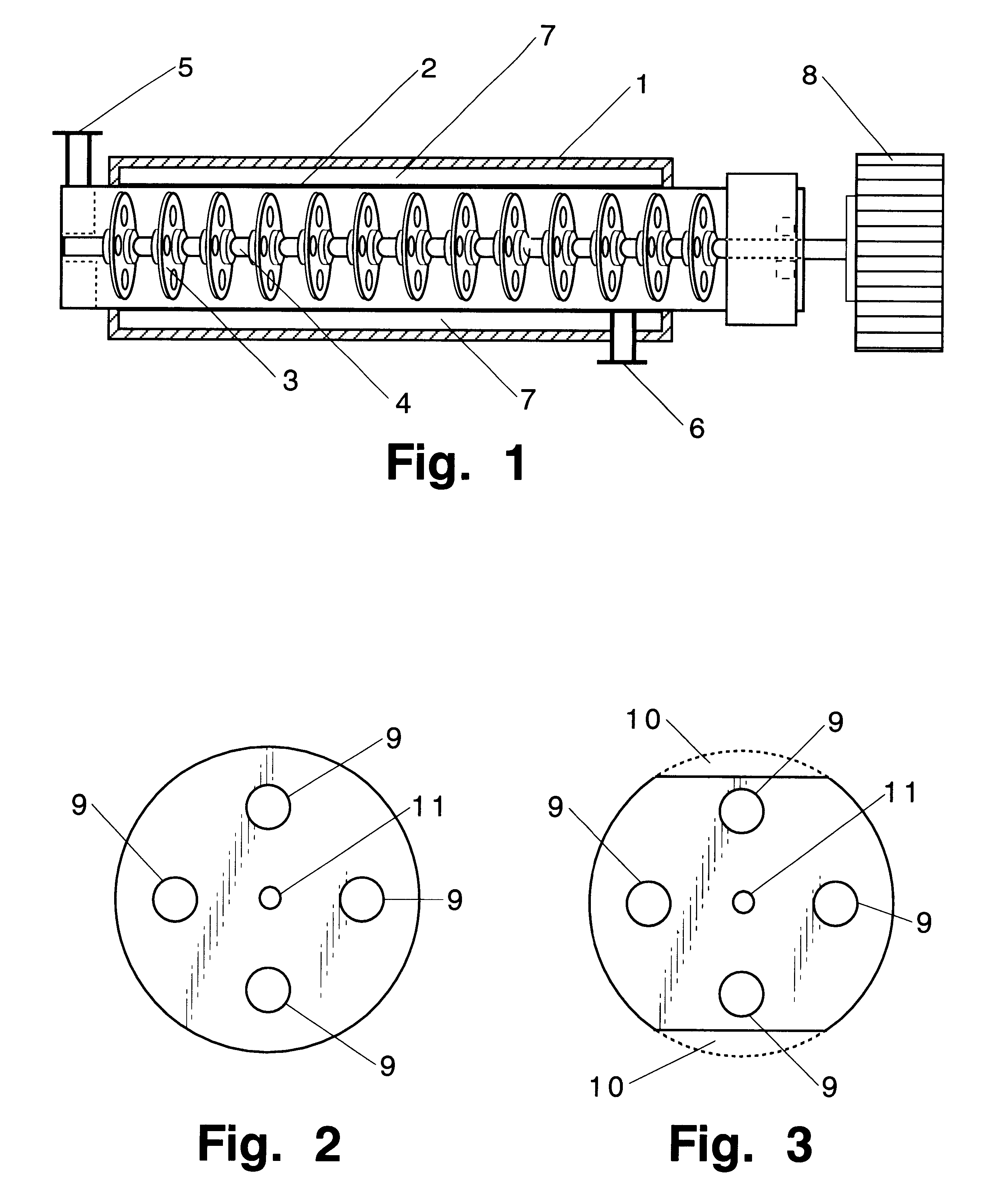
A tubular reactor 1 as shown in FIG. 4 was loaded with the following components: a copolymer of methylhydrogensiloxane and dimethylsiloxane having both molecular terminals capped with trimethylsiloxy groups represented by the following average formula Me.sub.3 SiO(Me.sub.2 SiO).sub.7 (MeHSiO).sub.3 SiMe.sub.3 and polyoxyethylene represented by the following formula HO(CH.sub.2 CH.sub.2 O).sub.12 CH.sub.2 CH.dbd.CH.sub.2. The first component was heated by feeding it to the reactor by means of feed pump 12 connected to heat-exchanger 15, and the second component was heated by feeding it to the reactor by means of feed pump 13 connected to heat-exchanger 16. After being mixed in dynamic mixer 17, both components were supplied to tubular reactor 1 in a continuous manner through raw-material feed port 5 located in the front part of reactor 1. The aforementioned copolymer and the polyether were introduced in a weight ratio of 3:7. Total feed rates are shown in Table 1. ...

example 2

Practical Example 2

The same raw material components as in Practical Example 1 in the same proportions as in Practical Example 1 were reacted in the same reactor 1 but with a static reactor 20 (with a 25 mm inner diameter, 3 m length, 1.5 liter capacity, and containing 60 elements) installed in a downstream position of reactor 1 (see FIG. 5). Reaction conditions and appearance of the reaction products are shown in Table 2.

It can be seen from Table 2 that when static reactor 20 is installed in the position downstream of tubular reactor 1, the hydrosilylation reaction can be completed with a residence time of 4 min. at a feed rate of 50 kg / hr.

example 3

Practical Example 3

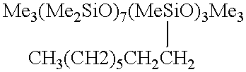
A tubular reactor 1 as shown in FIG. 4 was loaded with the following components: a copolymer of a methylhydrogensiloxane and dimethylsiloxane having both molecular terminals capped with trimethylsiloxy groups represented by the following average formula Me.sub.3 SiO(Me.sub.2 SiO).sub.7 (MeHSiO).sub.3 SiMe.sub.3 and 1-octene represented by the following formula: CH.sub.3 (CH.sub.2).sub.5 CH.dbd.CH.sub.2. The first component was heated by feeding it to the reactor by means of feed pump 12 through heat-exchanger 15, and the second component was heated by feeding it to the reactor by means of feed pump 13 through heat-exchanger 16. After being sufficiently mixed in dynamic mixer 17, both components were supplied to tubular reactor 1 in a continuous manner through raw-material feed port 5 located in the front part of reactor 1. The aforementioned copolymer and the 1-octene were fed in a weight ratio of 7:3. Total feed rates are shown in Table 3. At the same time, tubul...


PUM

PropertyMeasurementUnit
mole ratioaaaaaaaaaa
diameteraaaaaaaaaa
thicknessaaaaaaaaaa

Abstract

A continuous method for performing a hydrosilylation reaction comprising effecting a hydrosilylation reaction between a liquid organosilicon compound (A) having in each molecule at least one silicon-bonded hydrogen atom and a liquid organosilicon compound (B) having in each molecule at least one aliphatic unsaturated bond in the presence of a platinum catalyst (C) continuously in a tubular reactor equipped with a stirring and plug-flow maintaining apparatus located within the reactor.

Description

The present invention relates to a method for performing a continuous hydrosilylation reaction in a tubular reactor equipped with a stirring and plug-flow maintaining apparatus located within the reactor. The invention also relates to a method for continuous production of a modified liquid organosilicon compound.Hydrosilylation reactions conducted in the presence of a platinum catalyst between a liquid organic compound having in each molecule at least one aliphatic unsaturated bond and a liquid organosilicon compound having in each molecule at least one silicon-bonded hydrogen atom (hereinafter referred to as SiH) are normally carried out in a batch fashion in a compatible solvent (such as ethyl alcohol, isopropyl alcohol, or a similar alcohol; or benzene, toluene, xylene, or a similar aromatic solvent). It is normally required for the above reaction that the mole ratio of the aliphatic unsaturated bonds to SiH be greater than 1 and that the coefficient of conversion (1-{(amount of ...

Claims


Application Information

Patent Timeline
Patent Type & Authority Patents(United States)
IPC IPC(8): B01J19/20B01J19/18C08G77/06C08G77/00C08L83/04C08L83/00C07B61/00C07F7/18C08G77/38C08K3/10C08L71/00C08L83/05
CPCB01J19/1862B01J19/20C08L83/04C08G77/06B01J2219/00094B01J2219/00103B01J2219/00779B01J2219/182C08G77/12C08G77/20C08L83/00
Inventor OKUYAMA, TOSHIOMATSUI, NAOYATAKEMASA, TAKAO
Owner DOW TORAY CO LTD
Why Eureka
Try Eureka